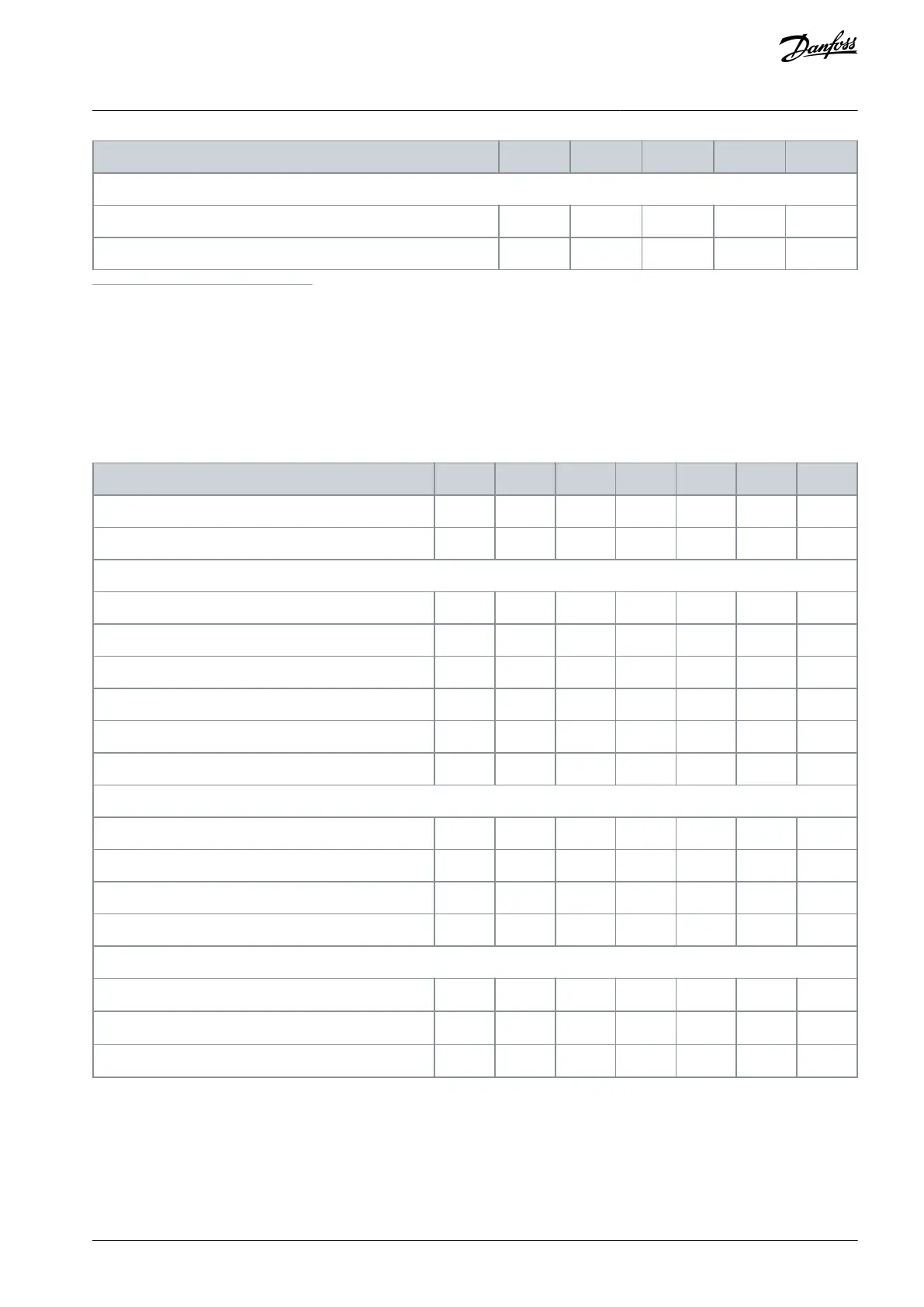
Power losses and efficiency
Estimated power loss at rated maximum load [W]
(1)
1
The typical power loss is at normal load conditions and expected to be within ±15% (tolerance relates to variety in voltage and cable conditions).
Values are based on a typical motor efficiency. Lower efficiency motors also add to the power loss in the drive and conversely. If the switching fre-
quency is raised from nominal, the power losses may rise significantly. LCP and typical control card power consumptions are included. Further op-
tions and customer load may add up to 30 W to the losses. (Though typically only 4 W extra for a fully loaded control card or options for slot A or slot
B, each). Although measurements are made with state-of-the-art equipment, some measurement inaccuracy must be allowed for (±5%).
2
Measured using 5m (16.4 ft) shielded motor cables at rated load and rated frequency
8.4 Electrical Data, 525–690 V
Table 52: Mains Supply 3x525–690 V AC, Normal Overload 110% for 1 Minute, P1K1–P7K5
Typical shaft output [kW]
Enclosure IP20/(UL Open Type
Continuous (3x525–550 V) [A]
Intermittent (3x525–550 V) [A]
Continuous (3x551–690 V) [A]
Intermittent (3x551–690 V) [A]
Continuous kVA 525 V AC [kVA]
Continuous kVA 690 V AC [kVA]
Continuous (3x525–550 V) [A]
Intermittent (3x52–550 V) [A]
Continuous (3x551–690 V) [A]
Intermittent (3x551–690 V) [A]
A2/A3 with mains disconnect [kA
rms
]
A4/A5 with mains disconnect [kA
rms
]
Without mains disconnect [kA
rms
]
AQ267037536117en-000101 / 130R0083 | 93Danfoss A/S © 2023.09
Specifications
VLT HVAC Drive FC 102
Operating Guide
 Loading...


