1.
2.
3.
•
•
•
•
•
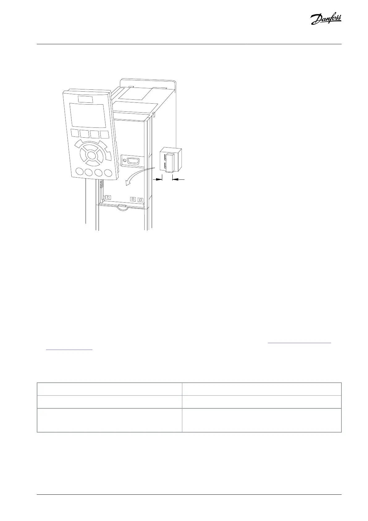
Procedure
Remove the LCP.
Remove any optional equipment covering the switches.
Set switches A53 and A54 to select the signal type. U selects voltage, I selects current.
4.8.7 Safe Torque Off (STO)
To run STO, additional wiring for the drive is required.
Refer to the VLT® Frequency Converters Safe Torque Off Operating Guide for further information.
4.8.8 RS485 Serial Communication
Up to 32 nodes can be connected as a bus or via drop cables from a common trunk line to 1 network segment. Repeaters can divide
network segments. Each repeater functions as a node within the segment in which it is installed. Each node connected within a
given network must have a unique node address across all segments.
Connect RS485 serial communication wiring to terminals (+) 68 and (-) 69.
Terminate each segment at both ends, using either the termination switch (bus term on/off, see 4.8.6 Voltage/Current Input
Selection (Switches)) on the drive, or as biased termination resistor network.
Connect a large surface of the shield to the ground, for example with a cable clamp or a conductive cable gland.
Apply potential-equalizing cables to maintain the same ground potential throughout the network.
Use the same type of cable throughout the entire network to prevent impedance mismatch.
Shielded twisted pair (STP)
Maximum cable length [m (ft)]
1200 (3937) (including drop lines)
500 (1640) station-to-station
4.9 Installation Check List
Before completing installation of the unit, inspect the entire installation as detailed in the following table. Check and mark the items
when completed.
AQ267037536117en-000101 / 130R0083 | 35Danfoss A/S © 2023.09
Electrical Installation
VLT HVAC Drive FC 102
Operating Guide

 Loading...


