•
•
•
•
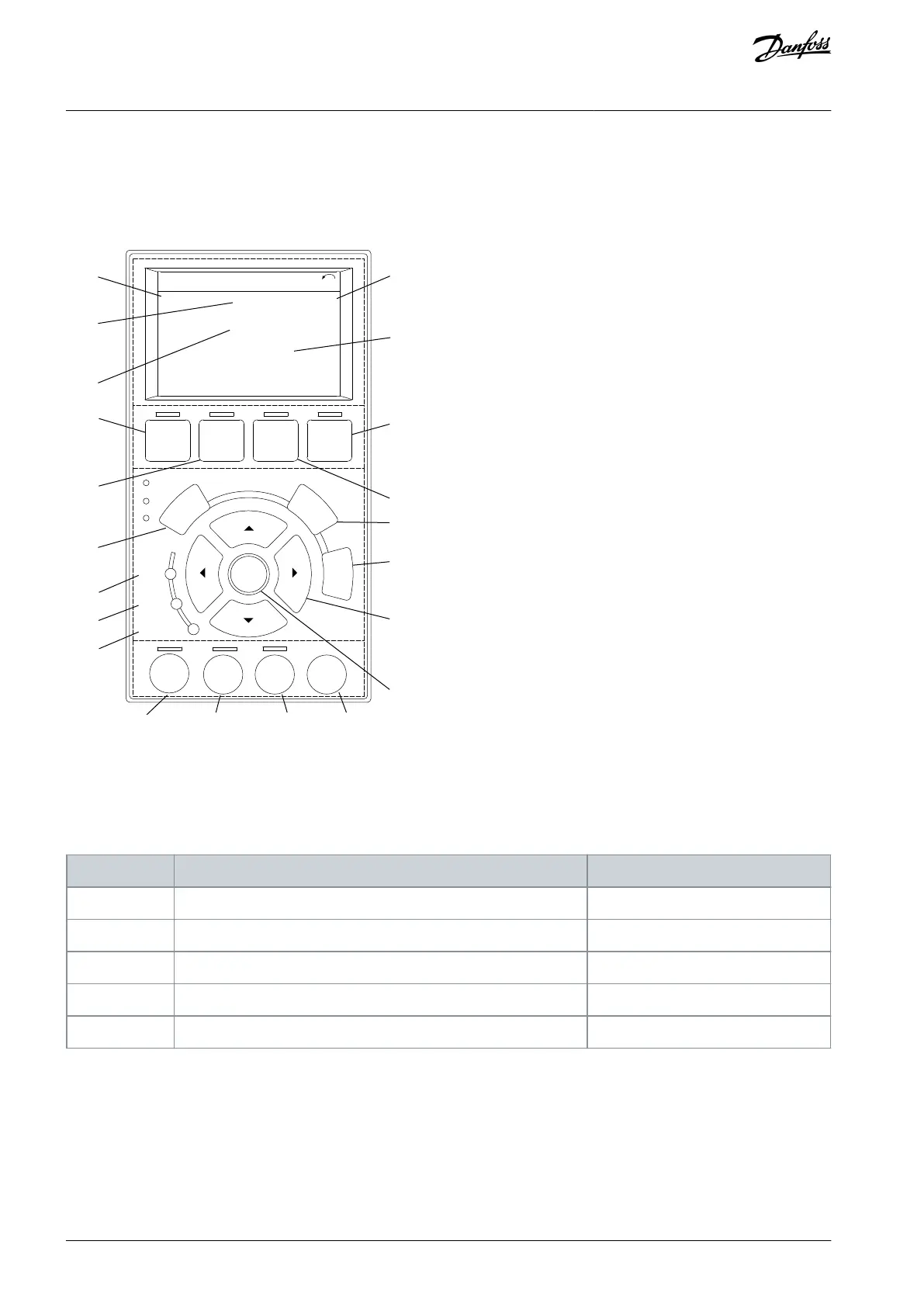
A: Display area
B: Display menus and keys
C: Navigation keys and indicator lights (LEDs)
D: Operation keys and reset
Auto
on
Reset
Hand
on
Off
Status
Quick
Menu
Main
Menu
Alarm
Log
Illustration 23: Local Control Panel (LCP)
Area A: Display area
The display area is activated when the drive receives power from mains voltage, a DC bus terminal, or a 24 V DC external supply.
The information shown on the LCP can be customized for user application. Select options in the Quick Menu Q3-13 Display Settings.
Table 12: Legend to Area A, Display Area
Parameter 0-20 Display Line 1.1 Small
Parameter 0-21 Display Line 1.2 Small
Parameter 0-22 Display Line 1.3 Small
Parameter 0-23 Display Line 2 Large
Parameter 0-24 Display Line 3 Large
Area B: Display menu keys
Menu keys are used for menu access for parameter set-up, toggling through status display modes during normal operation, and
viewing fault log data.
AQ267037536117en-000101 / 130R008338 | Danfoss A/S © 2023.09
Commissioning
VLT HVAC Drive FC 102
Operating Guide
 Loading...


