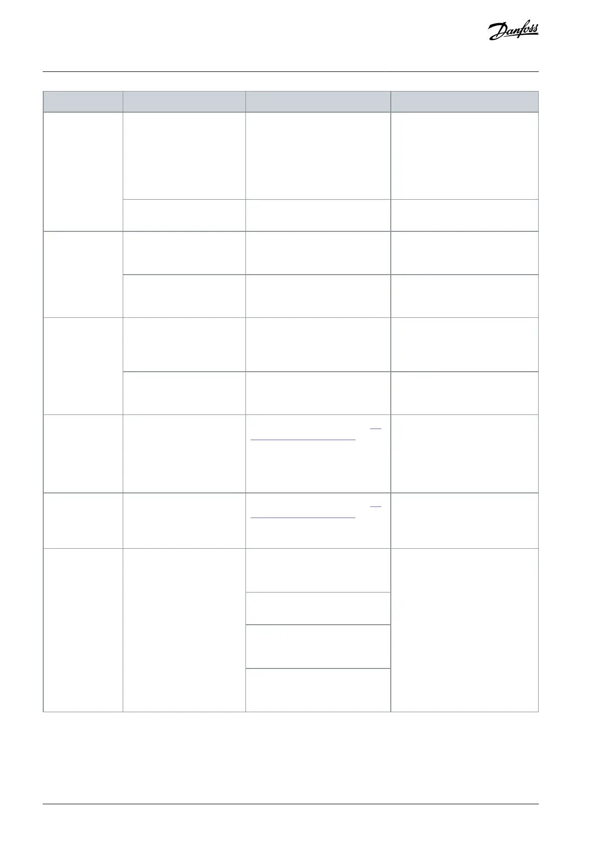
Motor is overloaded for the applica-
tion.
Perform start-up test and verify that
motor current is within the specifi-
cations. If motor current exceeds
nameplate full load current, the mo-
tor may run only with reduced load.
Review the specifications for the ap-
plication.
Perform a pre-start-up check to
check for loose connections.
Tighten loose connections.
Mains current im-
balance >3%.
Problem with mains power
(see alarm 4, Mains phase loss
description.
Rotate input power leads into the
drive by 1 position: A to B, B to C, C
to A.
If imbalanced leg follows the wire, it
is a power problem. Check mains
power supply.
Rotate input power leads in to drive
by 1 position: A to B, B to C, C to A.
If imbalanced leg stays on the same
input terminal, it is a problem with
the unit. Contact the supplier.
Motor current im-
balance >3%
Problem with motor or motor
wiring.
Rotate output motor leads by 1 po-
sition: U to V, V to W, W to U.
If imbalanced leg follows the wire,
the problem is in the motor or mo-
tor wiring. Check the motor and mo-
tor wiring.
Rotate output motor leads by 1 po-
sition: U to V, V to W, W to U.
If imbalanced leg stays on the same
output terminal, it is a problem with
the unit. Contact the supplier.
Drive acceleration
problems.
Motor data is entered incor-
rectly.
If warnings or alarms occur, see 7.6
List of Warnings and Alarms. Check
that motor data is entered correct-
ly.
Increase the ramp-up time in param-
eter 3-41 Ramp 1 Ramp Up Time. In-
crease current limit in parameter
4-18 Current Limi. Increase torque
limit in parameter4-16 Torque Limit
Motor Mode.
Drive deceleration
problems.
Motor data is entered incor-
rectly.
If warnings or alarms occur, see 7.6
List of Warnings and Alarms. Check
that motor data is entered correct-
ly.
Increase ramp-down time in param-
eter 3-42 Ramp 1 Ramp Down Time.
Enable overvoltage control in pa-
rameter 2-17 Over-voltage Control.
Acoustic noise or
vibration (for ex-
ample, a fan blade
is making noise or
vibrations at cer-
tain frequencies).
Resonance, for example in
the motor/fan system.
Bypass critical frequencies by using
parameters in parameter group 4-6*
Speed Bypass.
Check if noise and/or vibration have
been reduced to an acceptable limit.
Turn off overmodulation in parame-
ter 14-03 Overmodulation.
Change switching pattern and fre-
quency parameter group 14-0* In-
verter Switching.
Increase resonance dampening in
parameter 1-64 Resonance Dampen-
ing.
AQ267037536117en-000101 / 130R008384 | Danfoss A/S © 2023.09
Diagnostics and Troubleshooting
VLT HVAC Drive FC 102
Operating Guide
 Loading...


