[2] Analog Input 60 Use signals from analog input 60 as reference.
[11]
*
Local Bus Ref. Use signals from local bus as reference.
[21] LCP Potentiometer Use signals from LCP potentiometer as reference.
3-18 Relative Scaling Reference Source
Option: Function:
Select the source for a variable value to be added to the fixed
value defined in par. 3-14,
Preset Relative Reference
.
[0]
*
No Function The function is disabled
[1] Analog Input 53 Select analog input 53 as relative scaling reference source.
[2] Analog Input 54 Select analog input 54 as relative scaling reference source.
[8] Pulse Input 33 Select pulse input 33 as relative scaling reference source.
[11] Local Bus Ref. Select local bus ref. as relative scaling reference source.
[21] LCP Potentiometer Select LCP potentiometer as relative scaling reference source.
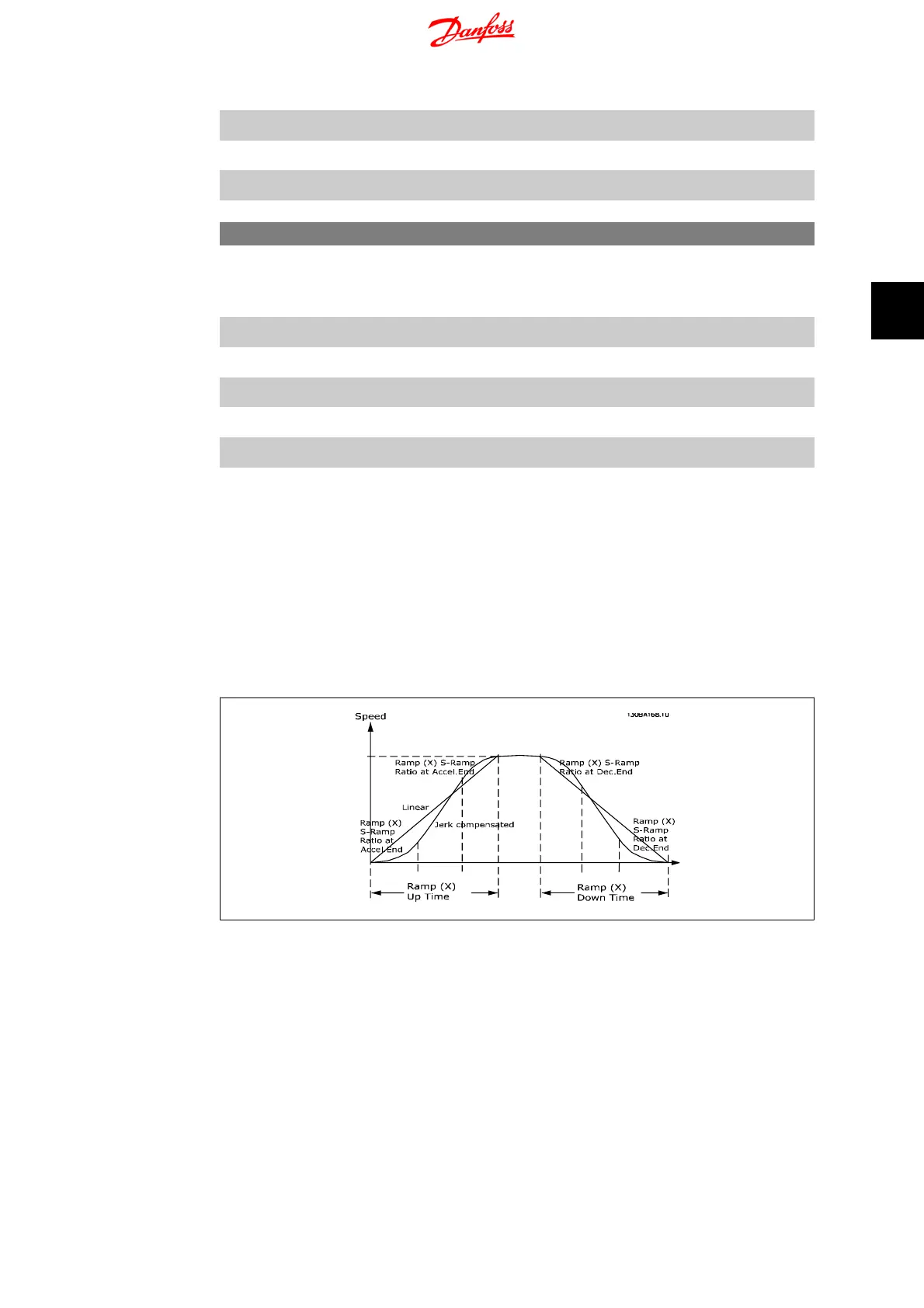
4.4.4. 3-4* Ramp 1
A linear ramp is characterized by ramping up at a constant speed until the desired motor speed
has been reached. Some overshoot may be experienced when reaching speed, which may cause
speed jerks for a short while before stabilizing.
An S-ramp accelerates more smoothly thus compensating for jerks when the speed is reached.
See the below figure for a comparison of the two ramp types.
Ramp Times:
Ramp up: Acceleration time. From 0 to nominal motor frequency (par. 1-23).
Ramp down: Deceleration time. From nominal motor frequency (par. 1-23) to 0.
Limitation:
Too short ramp up time can result in Torque limit warning (W12) and/or DC over voltage warning
(W7). Ramping is stopped when the frequency converter has reached Torque limit motor mode
(par. 4-16).
Too short ramp down time can result in Torque limit warning (W12) and/or DC over voltage
warning (W7). Ramping is stopped when the frequency converter reaches the Torque limit gen-
erator mode (par. 4-17) and/or the internal DC over voltage limit.
VLT Micro Drive FC 51 4. Parameter Descriptions
MG.02.C2.02 - VLT
®
is a registered Danfoss trademark
33
4
 Loading...


