3-14 Preset Relative Reference
Range: Function:
0.00% [-100.00 - 100.00%] Define fixed value in % to be added to variable value defined in
par. 3-18,
Relative Scaling Reference Source
.
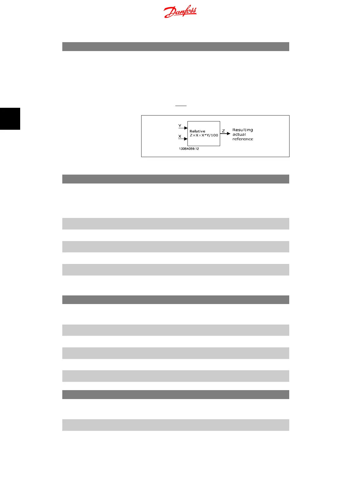
The sum of fixed and variable values (labelled Y in illustration
below) is multiplied with actual reference (labelled X in illusta-
tion). This product is added to actual reference
X
+
X
×
Y
100
3-15 Reference 1 Source
Option: Function:
Par. 3-15, 3-16 and 3-17 define up to three different reference
signals. The sum of these reference signals defines the actual
reference.
[0] No Function No reference signal is defined.
[1]
*
Analog Input 53 Use signals from analog input 53 as reference, see par. 6-1*.
[2] Analog Input 60 Use signals from analog input 60 as reference, see par. 6-2*.
[11] Local Bus Ref. Use signals from local bus as reference, see par. 8-9*.
[21] LCP Potentiometer Use signals from LCP potentiometer as reference, see par. 6-8*.
[8] Pulse input Use signals from pulse input as reference, see par. 5-5*.
3-16 Reference 2 Source
Option: Function:
See Par. 3-15 for description.
[0] No Function No reference signal is defined.
[1] Analog Input 53 Use signals from analog input 53 as reference.
[2]
*
Analog Input 60 Use signals from analog input 60 as reference.
[11] Local Bus Ref. Use signals from local bus as reference.
[21] LCP Potentiometer Use signals from LCP potentiometer as reference.
3-17 Reference 3 Source
Option: Function:
See Par. 3-15 for description.
[0] No Function No reference signal is defined.
[1] Analog Input 53 Use signals from analog input 53 as reference.
4. Parameter Descriptions VLT Micro Drive FC 51
32
MG.02.C2.02 - VLT
®
is a registered Danfoss trademark
4
 Loading...


