E
6/T3
2/T1
4/T2
5/L3
3/L2
1/L1
L3B
L2B
L1B
22
21
13
1)
1)
1)
14
24
33
34
06
05
08
07
17
18
25
11
16
A6
A5
A4
15
+
+
5
4
2
A
3
1
24
V DC
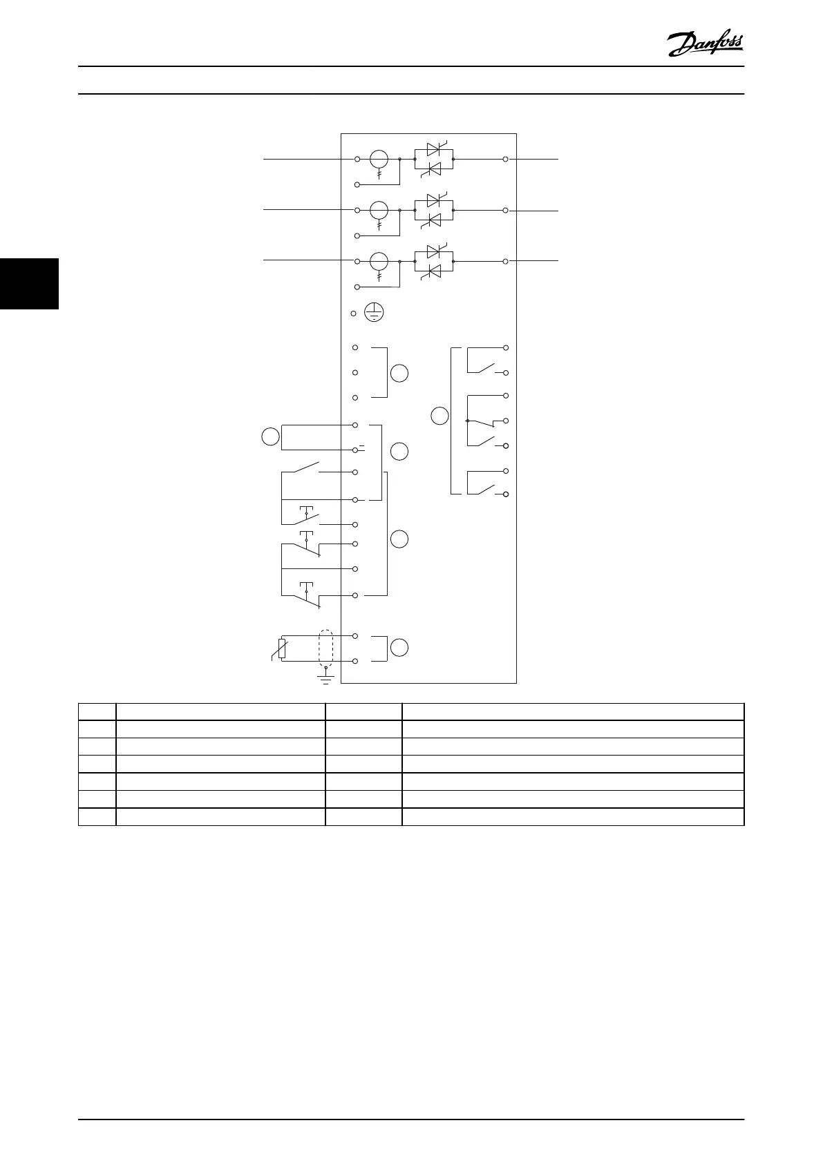
1 Control supply (model dependent) 11, 16 Programmable input
2 Outputs 15, 16 Start
3 Remote control inputs 17, 18 Stop
4 Motor thermistor input (PTC only) 25, 18 Reset
5 Relay outputs 13, 14 Relay output A
07, 08 Programmable analog output 21, 22, 24 Relay output B
16, 08 24 V DC output 33, 34 Relay output C
Illustration 4.19 Non-bypassed Models
1) MCD5-0245C current transformers are placed on the output. Bypass terminals are labeled T1B, T2B, and T3B.
Electrical Installation
VLT
®
Soft Starter MCD 500
34 Danfoss A/S © 05/2016 All rights reserved. MG17K602
44