NOTICE
Although Emergency run fullls the functionality requirements of Fire mode, Danfoss does not recommend its use in
situations that require testing and/or compliance with specic standards as it is not certied.
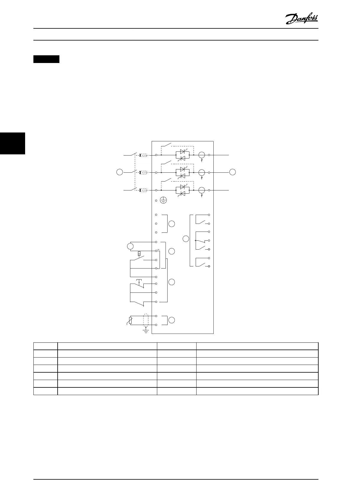
5.11 Auxiliary Trip Circuit
In normal operation, the VLT
®
Soft Starter MCD 500 is controlled via a remote 2-wire signal (terminals 17, 18).
Input A (terminals 11, 16) is connected to an external trip circuit (such as a low-pressure alarm switch for a pumping
system). When the external circuit activates, the soft starter trips and stops the motor.
K1
F
24
VD
22
21
6/T3
2/T1
13
14
4/T2
24
33
34
06
05
08
07
17
18
25
11
16
A6
A5
A4
5/L3
3/L2
15
S3
S1
S2
E
1/L1
+
+
5
6 7
4
2
A
3
1
177HA525.1
1 Control voltage (model dependent) S1 Start/stop contact
2 24 V DC output S2 Reset contact
3 Remote control inputs S3 Auxiliary trip contact
4 Motor thermistor input (PTC only) 13, 14 Relay output A
5 Relay outputs 21, 22, 24 Relay output B
6 3-phase supply 33, 34 Relay output C
7 Motor terminals
Illustration 5.13 Auxiliary Trip Circuit
Parameter settings:
•
Parameter 3-3 Input A Function.
- Select Input Trip (N/O) - assigns input A to auxiliary trip (N/O) function.
•
Parameter 3-4 Input A Name.
Product Features
VLT
®
Soft Starter MCD 500
46 Danfoss A/S © 05/2016 All rights reserved. MG17K602
55