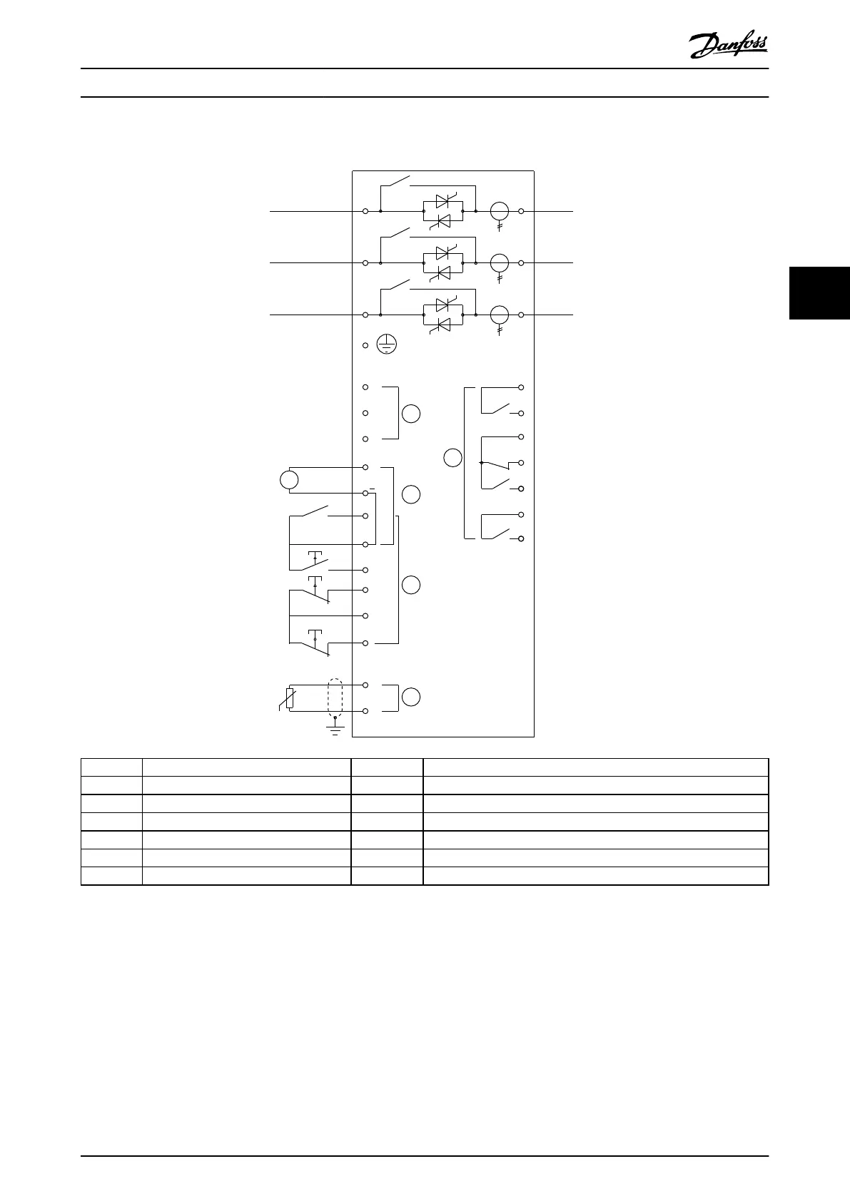
4.11 Schematic Diagrams
22
21
6/T3
2/T1
13
14
4/T2
24
33
34
06
05
08
07
17
18
25
11
16
A6
A5
A4
5/L3
3/L2
15
E
1/L1
+
24
V DC
5
4
2
A
3
1
177HA425.10
1 Control supply (model dependent) 11, 16 Programmable input
2 Outputs 15, 16 Start
3 Remote control inputs 17, 18 Stop
4 Motor thermistor input (PTC only) 25, 18 Reset
5 Relay outputs 13, 14 Relay output A
07, 08 Programmable analog output 21, 22, 24 Relay output B
16, 08 24 V DC output 33, 34 Relay output C
Illustration 4.18 Internally Bypassed Models
Electrical Installation Operating Guide
MG17K602 Danfoss A/S © 05/2016 All rights reserved. 33
4 4