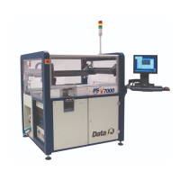
■ PSV7000 Machine Components ◘
PSV7000 Operator’s Manual —1—
back
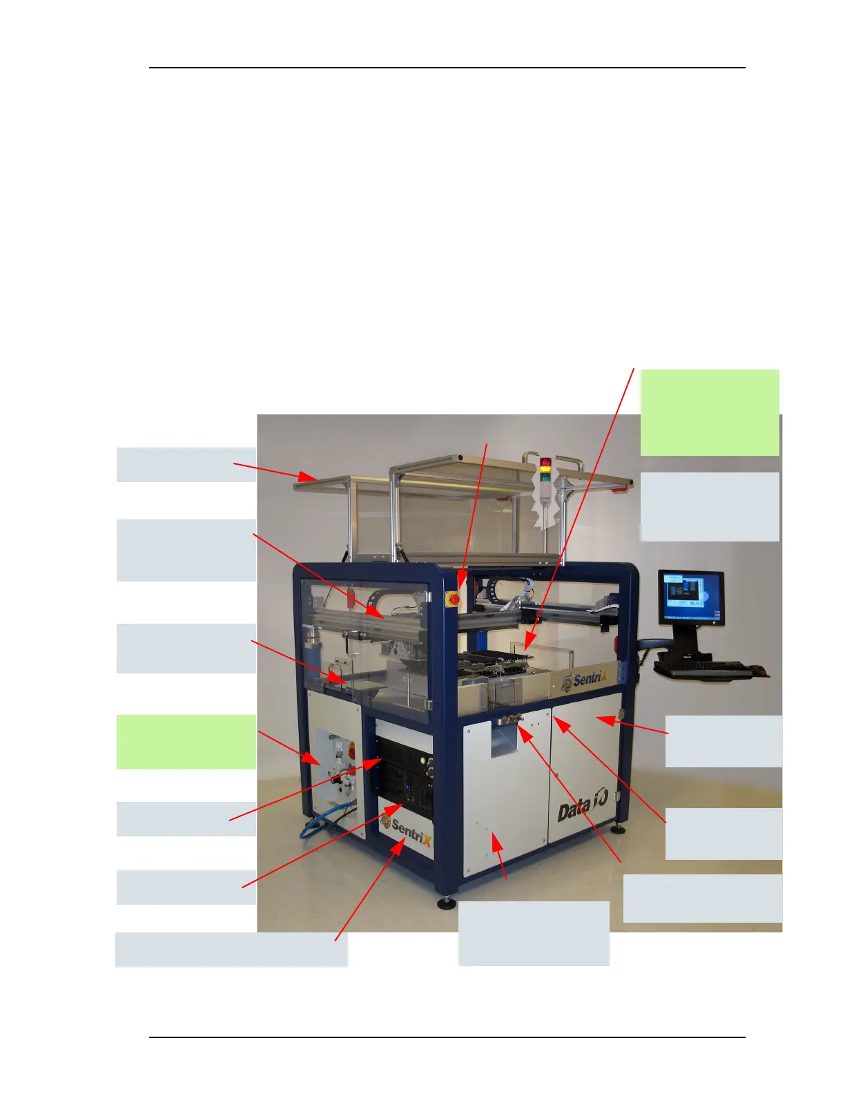
PSV7000 Machine Components
This Visual Index of PSV7000 features and subassemblies locates them on the machine
and in this manual.
Figure 1: The Big Picture—features of PSV7000.
Power Panel —see the
figure on page 3. ð
Support for Tape Feeder
and Vibratory Tube Media
Support and connec-
tion for Tray Feeder,
far side, not shown.
ESD connection;
page 2
Laser computer
1. E-Stops • page 10
2. Light Tower • page 67
3. Gantry & PNP head • see
Owner’s Manual
4. PNP head probes • page 38
5. Workspace
6. Tape Output • page 25
7. Tape Input • page 22;
Vibratory Tube Media •
page 21
8. Anti-static ground strap
connections • page 2
9. Monitor, keyboard, mouse
10. Handler Computer
11. Laser Computer • page 58
12. Programmers • page 2
13. Power Panel • page 3 and
Owner’s Manual for more
14. Safety doors
15. Access doors (front, two rear)
16. Take-Up spool for Tape-Input
• Contact Sales
17. 3D Coplanarity Inspection Sys-
tem computer
Gantry (supports PNP
head which is hidden
in this view)
The Work surface:
Input and Output
options. See the figure
on page 2.
Handler computer
2
1
5, 12
3, 4
13
11
10
7
8
9
Tape Output Module
mount
6
Safety doors
14
Access doors, one
front, two rear
15
Optional Tape Take-up
Module (not shown)
page 25
16
17
3D Coplanarity computer (not shown)