Operation ■ Running a Job on PSV7000
—46— Data I/O • 096-0461-001G
back
7» If Laser Marking—Installing the
Correct Rotor Tips
For jobs that use the laser marking option, the rotor tip must be of
adequate size for the vacuum to hold the device. Devices with flat
bottoms such as QFP, TSOP, and SSOP require tip diameters smaller
than the shortest edge of the device. The tips supplied on the machine
generally work for most devices. If you need different tips, follow the
steps below.
Requirements:
• No job is running.
• 1.5 mm hex key
• Machine power will need to be turned OFF.
CAUTION: Pinch Point! The Laser Rotor can rotate even when
the safety door is open (unless the rotor motor has been disabled).
The rotor rotates up very close to the PNP head if the head is
near.
When changing rotor tips, be sure the head is not near the Laser
Module and that at the laser motor is disabled with the Access
Cups command. Use caution.
To remove and install Laser rotor tips:
1. If the PNP head is near the Laser rotor, move it to the Tool posi-
tion. (Click RUN window > Tool).
2. At the RUN window, right-click the Laser indicator (rectangle)
and select submenu command Access cups. This disables the
rotor motor.
3. Open the rear safety door.
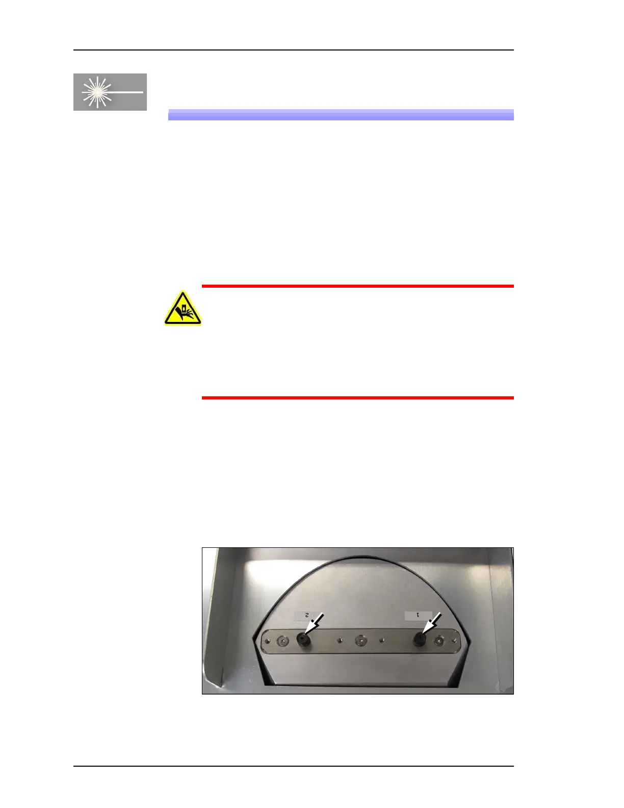
4. Unscrew each exposed tip with a 1 mm hex key in the center of
the tip, and lift each tip out.
Figure 28: A 1.5 mm hex key fits into the center of the each laser tip to
unscrew it.