AutoLab TF Dispenser Technical Manual – Revision 5
AutoLab TF dispensers Technical Manual TFTMTF / Rev 5.0 / 24
th
May 2006 Page 113 of 150
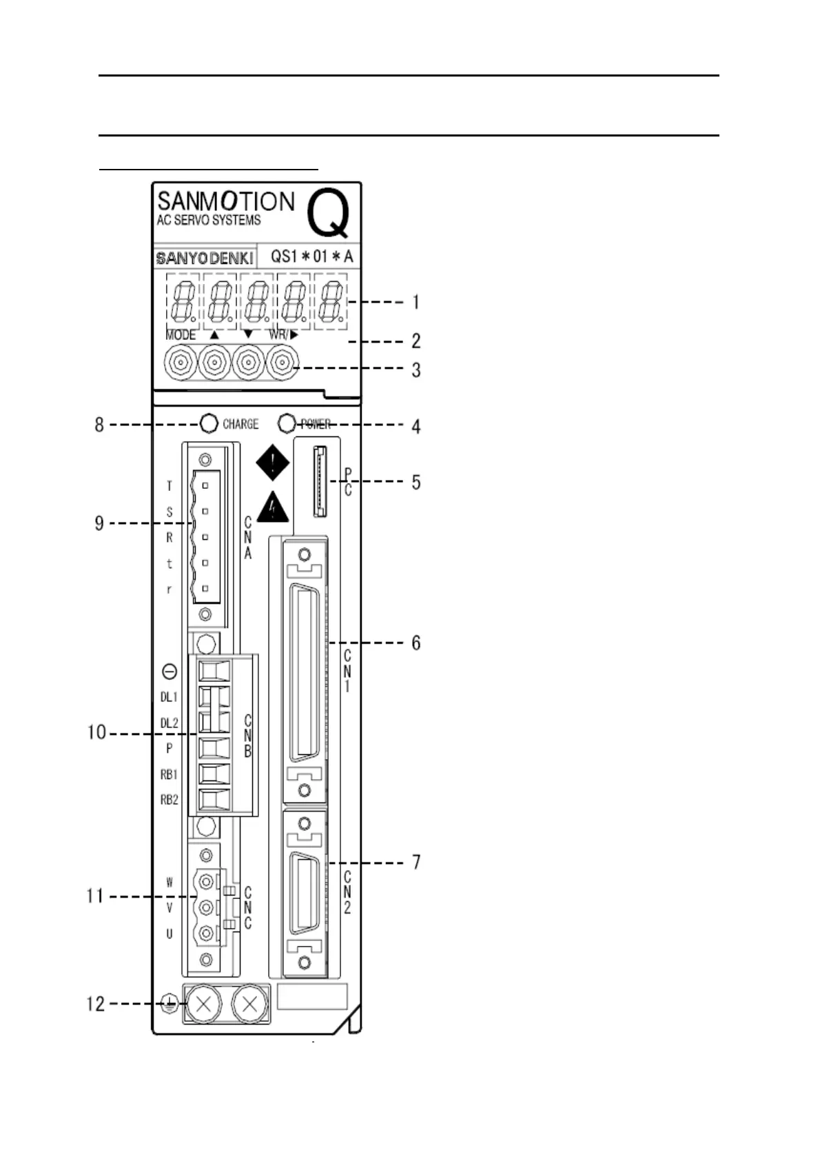
2-5-4 Sanyo Denki Q type amplifier
Name of Q type amplifier parts
1. 5 figures display 7 segment LED
- LED for display of digital operator
2. Digital operator
- Perform “Status display”, “Monitor”,
Test operation and adjustment”,
“Parameter editing” and “Alarm
display”.
3. Operation key
- Operation key of digital operator
4. Control power supply set-up LED
(POWER GREEN)
- Indicate the control power (r, t) is
supplied and control power supply +5V
is set up.
5. Connector for connecting PC interface
(PC)
- Used to perform “Status display”,
“Monitor”, Test operation and
adjustment”, “Parameter editing”,
“Alarm display” and “Operation Wave
form” by connecting PC interface
(Q-Setup).
6. Connector for general purpose
input/output (CN1)
- Used for I/O signal of servo amplifier
and upper unit (controller).
7. Connector for sensor signal (CN2)
- Connects sensor signal line from servo
motor.
8. Main power charge LED (CHARGE RED)
- Indicate the voltage is charging to the
smoothing capacity of main power.
9. Control power and Main power input
connectors (CNA)
- Connects the control cable to r and t
terminals and the Main power to R, S
and T
10. Connector for external regenerative
resistor and DC reactor (CNB)
- Connect an external regenerative
resistor between RB1 and RB2 and
DC reactor between DL1 and DL2. In
case DC reactor is not used, make
sure to short-circuit between DL1 and
DL2.
11. Servo motor power connector (CNC)
- Connect the servo motor power
connector.
12. Protective earth terminal
- Used for connecting protectively.
Grounds an earth cable for class D.

 Loading...