AutoLab TF Dispenser Technical Manual – Revision 5
AutoLab TF dispensers Technical Manual TFTMTF / Rev 5.0 / 24
th
May 2006 Page 108 of 150
2-5-3 Meaning of parameters in PV type amplifier
In this section will lead you to understand:
1. The meaning of parameters in servo amplifier.
2. When do you need to check the parameters
3. How to operate the Sanyo remote operator.
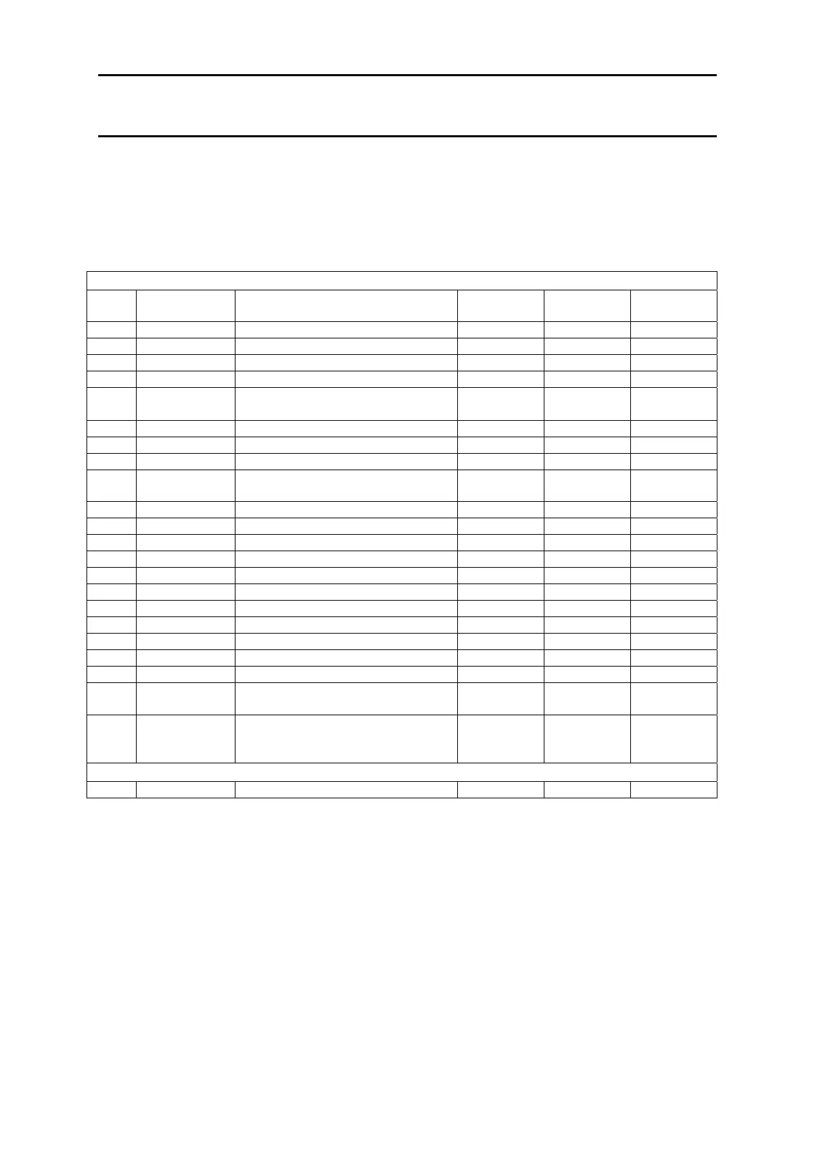
The below table of parameter setting is for your reference. The columns with blue color text
are the changing from default setting of amplifier.
Mode 0 Parameters
Page
No.
Abbreviation Name X Y Z
0 Kp Position loop gain 30 30 30
1 Kff Feed forward gain 0 0 0
2 Kvp Speed loop proportional gain
200 200 100
3 Tvi Speed loop integral time constant
20 25 10
4 INP Positioning completion signal
width
64 64 64
5 OVF Deviation excess 256 256 256
6 EGER Electronic gear ratio
25/1 10/1 5/1
7 ENCR Output pulse dividing ratio
1/25 1/10 1/5
9 PMOD Position command pulse train
type
00000000 00000000 00000000
10 UIF1 User I/F function selection 1
10000000 10000000 10100000
12 Func1 Selector switch1 00000000 00000000 00000000
13 Func2 Selector switch2 00000000 00000000 00000000
14 Func3 Selector switch3 00000000 00000000 00000000
15 Func4 Selector switch4
00000000 00000000 00000000
16 IILM Internal current limitation 100 100 100
17 SILM Sequence current limitation 120 120 120
18 FLPF Feed forward LPF 990 990 990
19 VLPF Speed command LPF 990 990 990
20 ILPF Current command LPF 500 500 500
21 IBEF Current command BEF 990 990 990
22 Tacc Speed acceleration/deceleration
time
0 0 0
23 TPcm Position command
acceleration/deceleration time
constant
0 0 0
Mode 1 Parameters
0 TYPE Control mode Position Position Position

 Loading...