Standard Cable Pinouts
Product Reference Guide
335
Standard Cable Pinouts
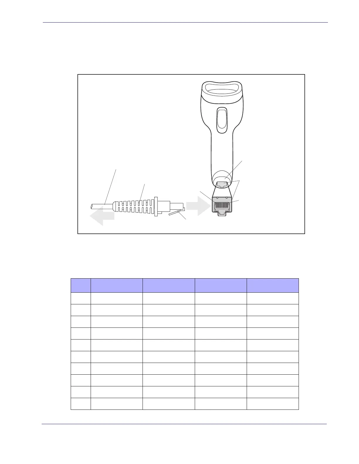
Figure 7 and Table 46 provide standard pinout information for the imager’s cable.
Figure 7. Standard Cable Pinouts
The signal descriptions in Table 46 apply to the connector on the imager and are for ref-
erence only.
Table 46.
Standard Cable Pinouts — Imager Side
Cable Clip (Latch)
To Host
Cable
Cable Strain Relief
Bottom of Imager
Interface Cable Port
Pin 1
Pin 10
Pin RS-232 OEM USB Keyboard Wedge
1 RTS (out)
2 D+ CLKIN (KBD side)
3 D- DATAIN (KBD side)
4 GND GND GND GND
5RX
6TX
7 VCC VCC VCC VCC
8 IBM_B CLKOUT (PC side)
9 IBM_A DATAOUT (PC side)
10 CTS (in)
 Loading...