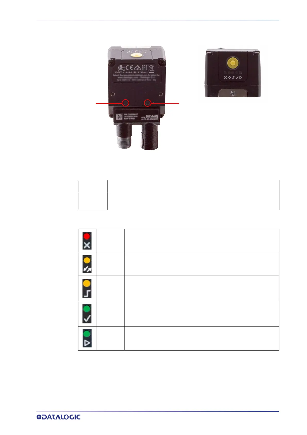
INDICATOR AND KEYPAD BUTTON
PRODUCT REFERENCE GUIDE 22
INDICATOR AND KEYPAD BUTTON
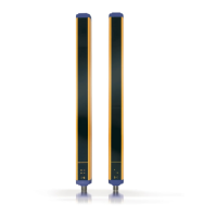
Figure 6 - Indicators
The following LED indicators are located on the device:
The colors and meaning of the five LEDs are illustrated in the following table:
During device startup (reset or restart phase), these five LEDs blink for one second.
PWR
blue LED indicates that the device is connected to the power supply (Figure 6, 1)
NET
yellow LED indicates connection to the on-board Ethernet network (Figure
6, 2)
NO GOOD
red LED indicates a NO GOOD object. Blinking during Teaching (Fig-
ure 6, 3)
for future use (Figure 6, 4)
TRIGGER
yellow LED indicates trigger input status in Teach phase, and trigger
received in Run phase (Figure 6, 5)
GOOD
green LED indicates a GOOD object. Blinking during Teaching (Figure
6, 6)
RUN
green LED indicates that the device is in Run phase. If blinking, it
indicates that Teaching is required (Figure 6, 7)
1
2
3
4 5
6
7