ELECTRICAL CONNECTIONS
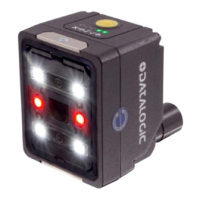
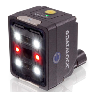
31 SMART-VS PLUS
Previous Smart-VS Plus versions use CAB-GDxx cables that terminate in an M12 17-pin
connector on the Smart-VS Plus side and 17 stripped wires on the other side. These
wires have the following functionalities:
POWER SUPPLY
The power must be between 10 and 30 Vdc only.
INPUTS
There are two optocoupled polarity insensitive inputs available on the reader: Input 1
(External Trigger) and Input 2 (Remote Button).
The External Trigger is necessary to start acquiring and processing images.
The Remote Button installation is recommended in cases where the device is not acces-
sible and, in general, to have easier access to the Teaching function.
The electrical features of both inputs are:
V
AB
= 30 Vdc max.
I
IN
= 10 mA max.
The active state of these inputs are selected in software.
An anti-disturbance filter, by default, is implemented in software on both inputs. The
value can be changed through the software parameter Debounce Filter. See "
I/O Set-
tings" on page 19
or refer to the Settings section of the Smart-VS WebApp User’s Guide
for further details on these parameters.
POWER AND I/O CONNECTOR PINOUT
(cables with 17 stripped wires)
PIN NAME COLOR DESCRIPTION
1 Vdc Brown Power supply input voltage +
2 GND Blue Power supply input voltage -
Connector
case
Chassis
Connector case provides
electrical connection to chassis
6 I1A Yellow I1A Trigger Input A (polarity insensitive)
5 I1B Pink I1B Trigger Input B (polarity insensitive)
13 I2A White/Green I2A Remote Teach A (polarity insensitive)
3 I2B White I2B Remote Teach B (polarity insensitive)
9 O1 Red Data Valid PP
8 O2 Gray GOOD Output PP
16 O3 Yellow/Brown NO GOOD Output PP
WARNING: For proper installation, it is recommended to trim out all unused
wires.
NOTE: Each time the Smart-VS Plus is powered on, the electronic focus
motor system does extra work for system checking and setup. It is recom-
mended to limit power cycles to a few times per day.