PRODUCT REFERENCE GUIDE 30
CHAPTER 4
ELECTRICAL CONNECTIONS
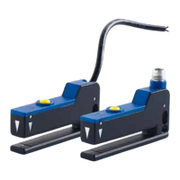
Smart-VS Plus can be connected through one of the available CAB-GDxx accessory
cables.
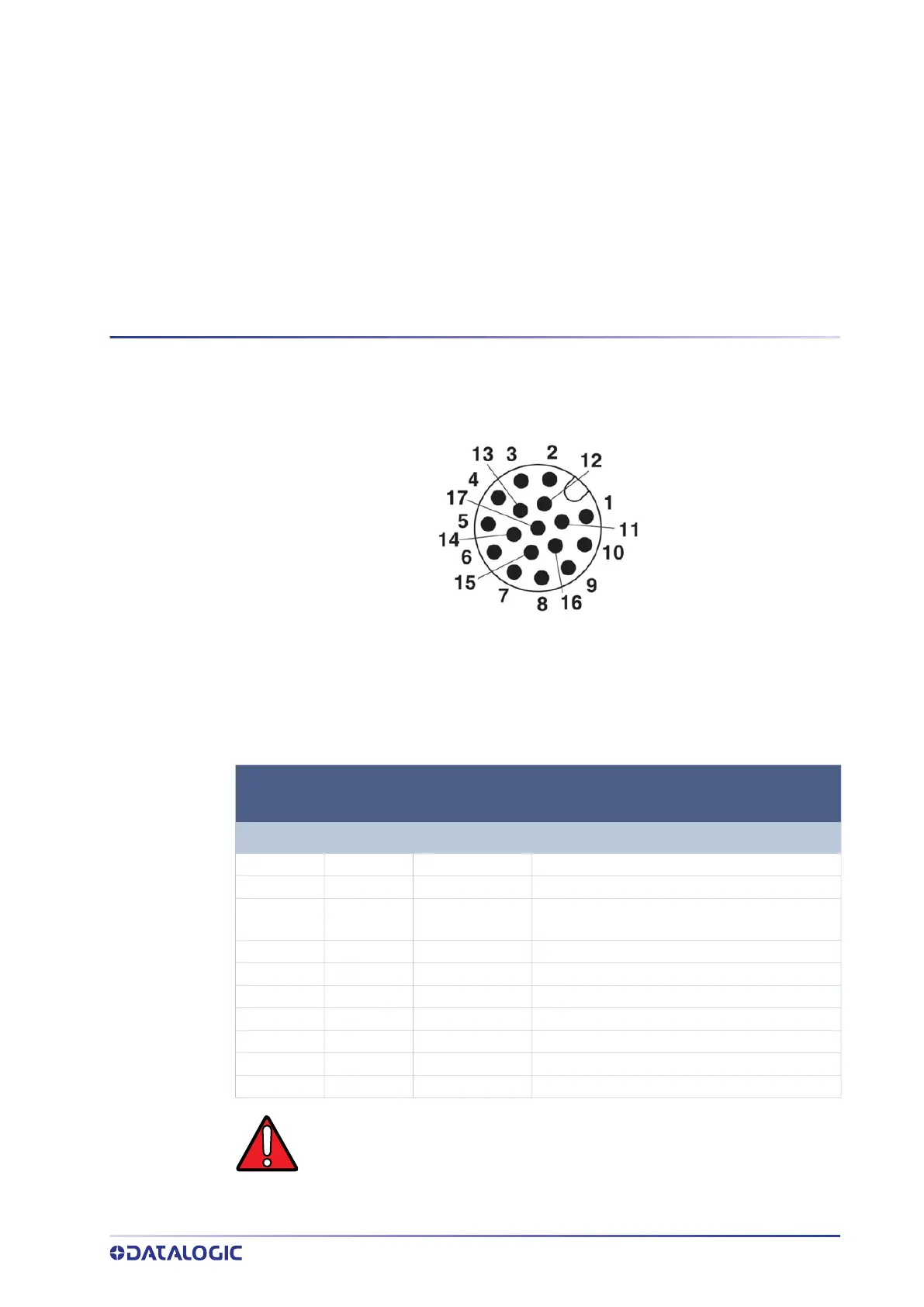
Figure 14 - M12 17-pin Power and I/O Connector
The recommended cables 95A900052 and 95A900053 (refer to "Accessories" on page
24
) terminate in an M12 17-pin connector on the Smart-VS Plus side and 9 stripped
wires on the other side. These wires have the following functionalities:
POWER AND I/O CONNECTOR PINOUT
(cables with 9 stripped wires)
PIN NAME COLOR DESCRIPTION
1 Vdc Brown Power supply input voltage +
2 GND Blue Power supply input voltage -
Connector
case
Chassis
Connector case provides
electrical connection to chassis
6 I1A Yellow I1A Trigger Input A (polarity insensitive)
5 I1B Pink I1B Trigger Input B (polarity insensitive)
13 I2A Green I2A Remote Teach A (polarity insensitive)
3 I2B White I2B Remote Teach B (polarity insensitive)
9 O1 Red Data Valid PP
8 O2 Gray GOOD Output PP
16 O3 Black NO GOOD Output PP
WARNING: For proper installation, it is recommended to trim out all unused
wires.