DATAVS2-VSM INSTRUCTION MANUAL
3 ELECTRICAL CONNECTIONS
3.1 PINOUTS
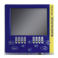
3.1.1 DataVS2 OBJ/AOR Sensor
M12 Reverse Keyed 4-Pin Male
(Ethernet connection)
pin 1: Ethernet RX+
pin 2: Ethernet TX+
pin 3: Ethernet RX-
pin 4: Ethernet TX-
M12 8-Pin Male
(power supply and I/O)
pin 1: white : Digital Input 1
pin 2: brown: +24 Vdc
pin 3: green : Output 4 /
Strobe for external illuminator
pin 4: yellow: Output 1
pin 5: grey: Output 2
pin 6: pink: Output 3
pin 7: blue: Ground
pin 8: red: External Trigger
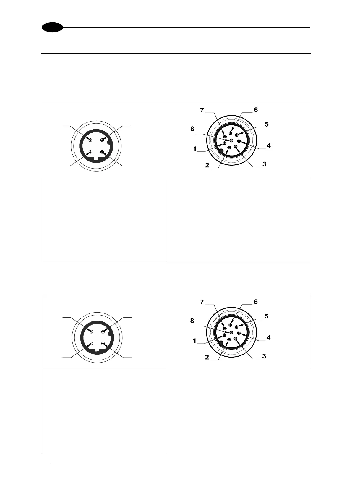
3.1.2 DataVS2 ID/PRO Sensor
M12 Reverse Keyed 4-Pin Male
(Ethernet connection)
pin 1: Ethernet RX+
pin 2: Ethernet TX+
pin 3: Ethernet RX-
pin 4: Ethernet TX-
M12 8-Pin Male
(power supply and I/O)
pin 1: white : RS-232 Rx
pin 2: brown: +24 Vdc
pin 3: green : Output 4 /
Strobe for External Illuminator
pin 4: yellow: Output 1
pin 5: grey: Output 2
pin 6: pink : RS-232 Tx
pin 7: blue: Ground
pin 8: red: External Trigger
 Loading...