Maintenance M7/M7L/M7LT Modular Satellite Modem
3-40 M7/M7L/M7LT - Rev. 0.05
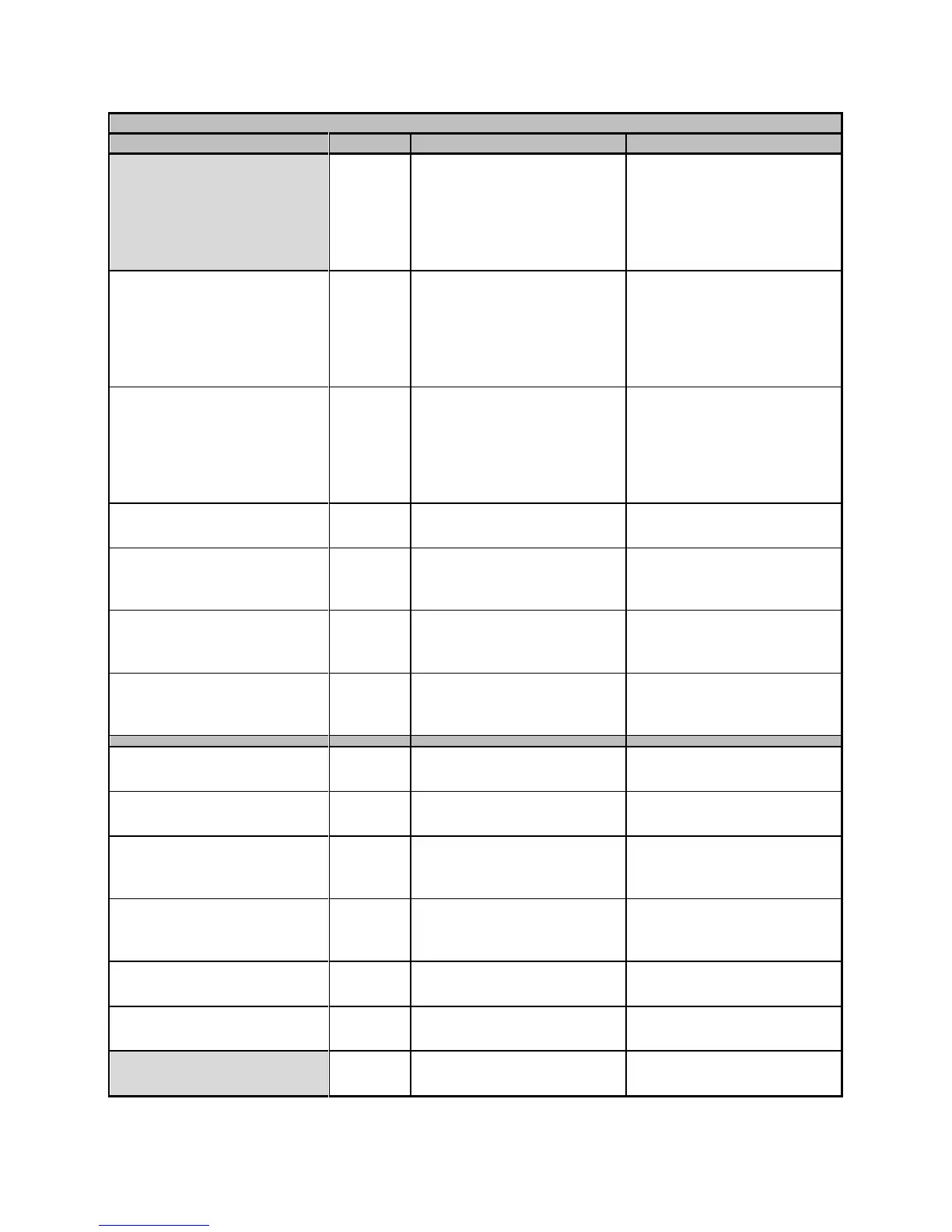
Alarm OCXO Oven Mask
Mute & Alarm A
0=None, 1=to Alarm A, 2=to
Alarm B, 3=to Alarm A & B,
4 = Mute CXR, 5 = Mute CXR
& Alarm A, 6 = Mute CXR &
Alarm B, 7 = Mute CXR &
Alarm A & B
Selects destination of alarm.
M7LT only
Alarm Monitor Input Mask
None
0=None, 1=to Alarm A, 2=to
Alarm B, 3=to Alarm A & B,
4 = Mute CXR, 5 = Mute CXR
& Alarm A, 6 = Mute CXR &
Alarm B, 7 = Mute CXR &
Alarm A & B
Selects destination and action
taken for the analog input
alarm.
Alarm Power Supply Mask
to Alarm A & B
0=None, 1=to Alarm A, 2=to
Alarm B, 3=to Alarm A & B,
4 = Mute CXR, 5 = Mute CXR
& Alarm A, 6 = Mute CXR &
Alarm B, 7 = Mute CXR &
Alarm A & B
Selects destination and action
taken for the input power DC
voltage threshold alarm.
Alarm Power Supply Min
+8.0 V
+7.6V to +34.0V in 0.1V steps
Threshold setting for the input
power DC voltage alarm.
Alarm Beep Mask
On Alarm A & B
0=None, 1=On Alarm A,
2=On Alarm B,
3=On Alarm A & B
Selects if alarm causes a unit
audible “beep”.
Alarm Test Active Mask
to Alarm A
0=None, 1=to Alarm A,
2=to Alarm B,
3=to Alarm A & B
Selects destination of alarm
Alarm Hardware Mask
to Alarm A
0=None, 1=to Alarm A,
2=to Alarm B,
3=to Alarm A & B
Selects destination of alarm
0 = Disabled,
1 = Lamp Test
Carrier output mode for test
purposes.
Test Firmware Flash 1
2.30i1 - Running
Read only indication of the
current operating Firmware
Test Firmware Flash 2
2.30i1
Read only indication of the
pending or recently updated
firmware.
Idle, Downloading, Verifying,
Installing,
Read only indication of the
current state of the firmware
installer
Test Power Supply
+24.2 V
Real time input power DC
voltage monitor
Test Monitor Input
+24.2 V
Real time analog input voltage
monitor on pin 4 of J6
Test OCXO Temperature
+90.0°C
Real time OCXO temperature
monitor. M7LT only