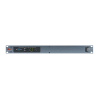
Configuring the DriveRack™
Section 3
DriveRack
™
17
and rotating (to change values), the DATA wheel.
• If Custom Post-effects linking is selected, depending on the current configuration, you will be allowed to
link post effects to specific outputs. The following illustration shows the post effects linking, utilizing a 2X4
crossover:
• Pressing the DATA wheel will move the cursor to the parameter to be edited, and rotating the DATA
wheel will either Link (L) or Unlink (U) the effect to the selected outputs
• Once you have edited and moved through the three post crossover effect modules, the next display will
appear as follows:
Note on linking dynamics- Linked compressors share a common RMS (or signal) detector so that a
high range on one linked channel will cause gain reduction on all of the linked channels.
Once you have edited and moved through the three post crossover effect modules, the next display
will appear as follows:
• If you select Standard output routing, pressing the DATA wheel take you directly to the load page. If how-
ever, you choose to not select standard output routing, the next page will appear as follows:
• Now you can proceed to route any digital output to any analog output. This means that the digital
output signal can be routed to any one of the 4 physical outputs.
Output routing selections can be made by pressing (to select output 1-4)) the DATA wheel and
rotating the DATA wheel (to change analog outputs).
• Once your output routing has been selected, press the NEXT PG button and the display will
appear as follows: