Cabling the second optional DAE to create back-end bus 0
Connect the second optional expansion DAE to the DPE expansion port 0 to extend
back-end bus 0 (BE0) and designate this DAE as enclosure 0 of this bus. We refer to
the address of this enclosure as BE0 Enclosure 0 (0_0).
When cabling the 15-drive DAE LCC SAS ports, ensure that the cables do not overlap
behind the DAE.
Procedure
1. Label a pair of mini-SAS HD cables.
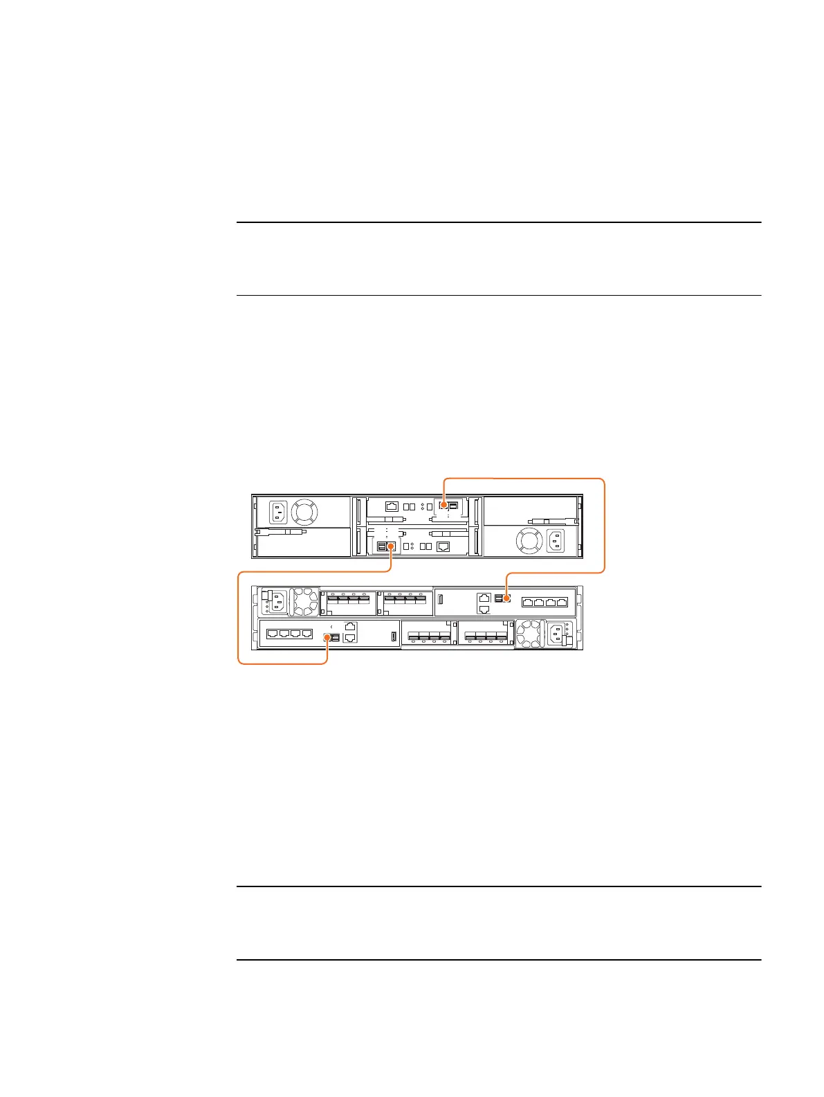
2. Connect port 0 on SP A in the bottom slot of the DPE to port A on the link
control card (LCC A) in the bottom of the DAE.
3. Connect port 0 on SP B in the top slot of the DPE to port A on the link control
card (LCC B) in the top of the DAE.
Figure 23 Cabling a DPE to a second 25-drive DAE
After you finish
If you need to cable more than two optional DAEs, refer to the
Unity Installation Guide
.
Cabling an expansion DAE to an existing DAE to extend a
back-end bus
Connect the optional expansion DAE to the last installed DAE in the back-end bus to
extend to the new DAE.
When cabling the 15-drive DAE LCC SAS ports, ensure that the cables do not overlap
behind the DAE.
Procedure
1. Label a pair of mini-SAS HD cables.
Installation Procedures
Cabling the second optional DAE to create back-end bus 0 37
 Loading...
