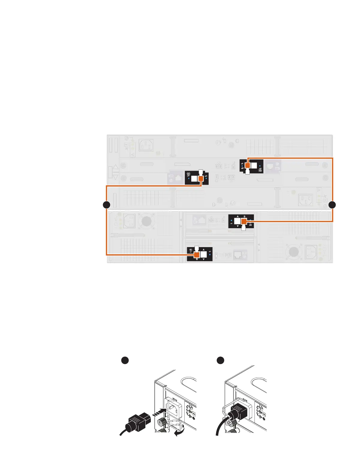
2. Connect port B on the link control card (LCC A) of the lower-numbered DAE to
port A on the link control card (LCC A) of the higher-numbered DAE.
LCC A is on the lower portion of the DAE.
3. Connect port B on the link control card (LCC B) of the lower-numbered DAE to
port A on the link control card (LCC B) of the higher-numbered DAE.
LCC B is on the upper portion of the DAE.
Example 1 Connect the DAE to another DAE
Figure 24 25-drive DAE extended to a 15-drive DAE
0 1
0
1
x4x4
x4
x4
x4 x4
A
B
AB
A
B
A
B
x4
x4
1
2
Connecting power to the DAE
Procedure
1. Verify that the cabinet circuit breakers are in the On position and that power is
connected to the cabinet.
2. Connect the power cables to the optional DAEs.
Figure 25
Connecting power cables to the 3U, 15-drive DAE
Installation Procedures
38 Unity 480/F, Unity 680/F, Unity 880/F Installation and Service Guide
 Loading...
