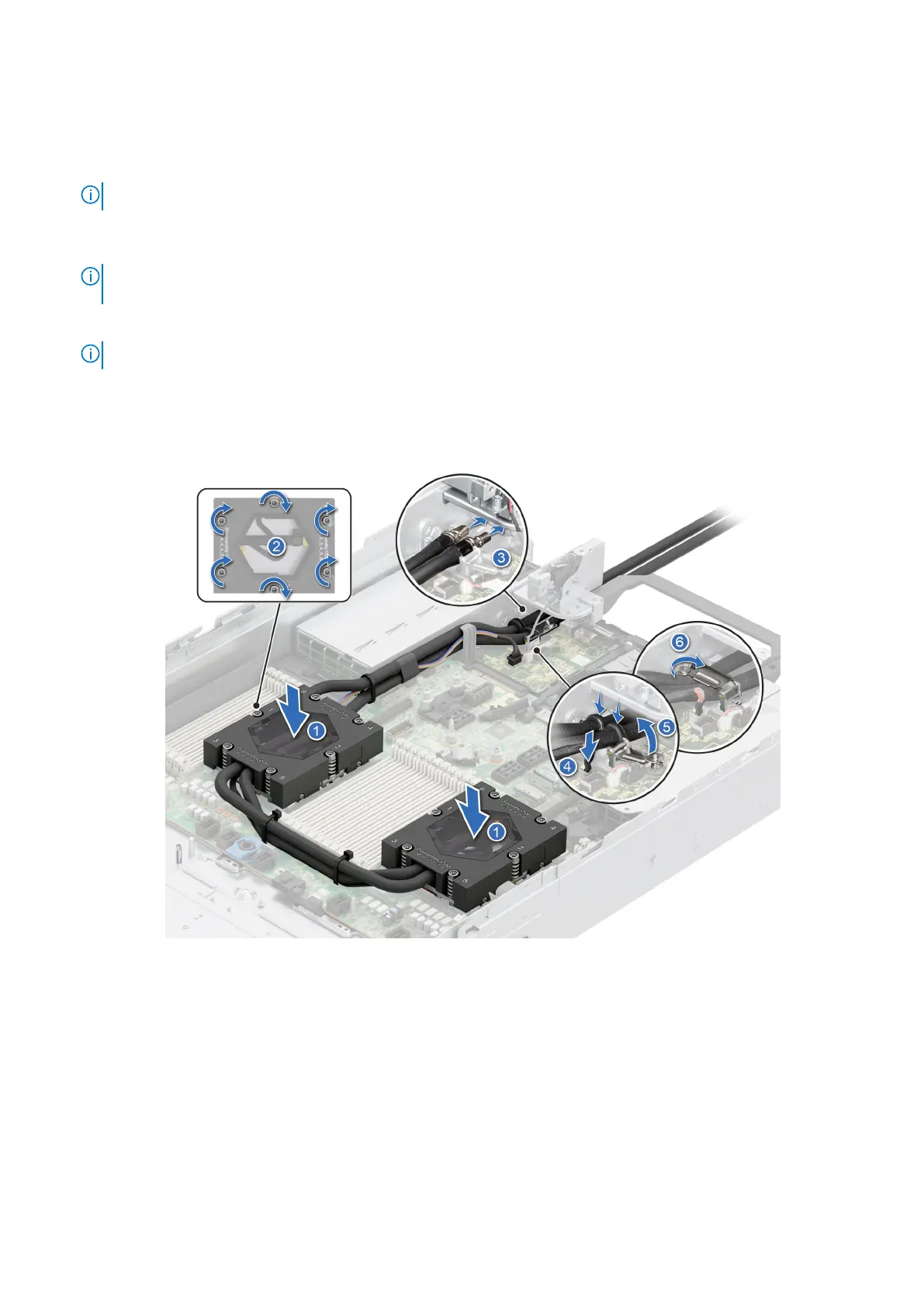
2. Place the module on the processor slot and set all the anti-tilt wires to locked position (outward position).
3. Route the DLC tubes to the front of the system and along the DIMM latches.
4. Using a Torx #T20 screwdriver, fully tighten the captive screw all the way down before moving to the next screw (on
one-screw-at-a-time basis).
NOTE: Follow the screw sequence defined on heat sink label. Assembly order: 1, 2, 3, 4, 5, 6.
5. The tubes leading towards the rear of the chassis and the DLC leak detection cable are placed in between the PSU 2 and the
clip of rear I/O board (RIO).
NOTE: Leak detection cable must be placed first into the clip (underneath the cooling tubes), and then place tube 2 and
tube 1 into the clip to ensure that cable does not interfere with the PCIe risers.
6. Route the rear end of the DLC tubes through the RIO board.
NOTE: Follow the number labels on the DLC tubes and ring holders (1,2).
7. Connect the DLC leak detection cable to the connector on RIO.
8. Align the rubber ring on the tubes with the ring holder.
9. Tilt the DLC ring holder and using a Phillips #2 screwdriver, tighten the captive screw on the DLC ring holder to secure it in
place.
Figure 123. Installing the liquid cooling heat sink
Next steps
1. If removed, install the air shroud.
2. Follow the procedure listed in the After working inside your system.
Installing and removing system components
155
 Loading...