Chapter 4 Parameters|VFD-VL
4-58
10V5123 4-1-2-3-4-5-10 V 6 7 8 9
03-00
to
03-02
-6-7-8
-9
0
1
2
3
44
2
2
4
2
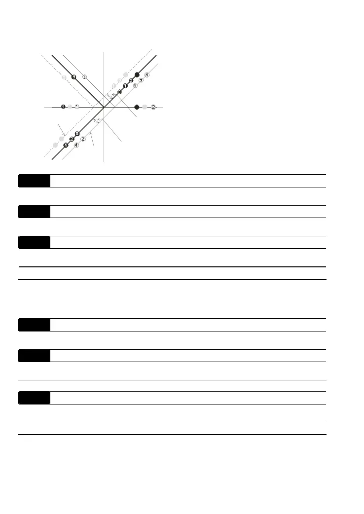
03-09~03-11 gain is positive
4
Zero bias
Serve bias as the center, lower than bias =bias
Serve bias as the center, greater than bias=bias
The absolute value of the bias voltage
while serving as the center (unipolar)
Serve bias as the center(unipolar)
bias
bias
Positive bias
Negative bias
03-09
Analog Input Gain 1 (AUI1)
Control
mode
VF VFPG SVC FOCPG TQCPG FOCPM
Factory setting: 100.0
03-10
Analog Input Gain 1 (ACI)
Control
mode
VF VFPG SVC FOCPG TQCPG FOCPM
Factory setting: 100.0
03-11
Analog Input Gain 1 (AUI2)
Control
mode
VF VFPG SVC FOCPG TQCPG FOCPM
Factory setting: 100.0
Settings 0.0~500.0%
Parameters 03-03 to 03-11 are used when the source of frequency command is the analog
voltage/current signal.
03-12
Analog Input Delay Time (AUI1)
Control
mode
VF VFPG SVC FOCPG TQCPG FOCPM
Factory setting: 0.01
03-13
Analog Input Delay Time (ACI)
Control
mode
VF VFPG SVC FOCPG TQCPG FOCPM
Factory setting: 0.01
03-14
Analog Input Delay Time (AUI2)
Control
mode
VF VFPG SVC FOCPG TQCPG FOCPM
Factory setting: 0.01
Settings 0.00 to 2.00 sec
Interferences commonly exist with analog signals, such as those entering AUI, ACI and AUI2.
These interferences constantly affect the stability of analog control and using the Input Noise
Filter will create a more stable system.
Call 1(800)985-6929 for Sales
Call 1(800)985-6929 for Sales

 Loading...


