Appendix B Accessories|VFD-VL
B-21
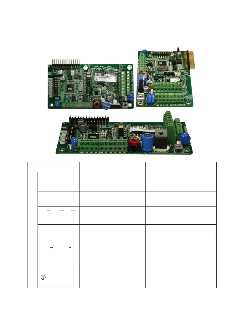
B.8 PG Card (for Encoder)
B.8.1 EMVL-PGABL-1
1. Terminals descriptions
Terminal Symbols Descriptions Specifications
VP
Power source of encoder (use
SW2 to switch 12V/5V)
Voltage: +5V±0.5V or +12V±1V
Current: 200mA max.
0V
Power source common for
encoder
Reference level of the power of
encoder
A, , B, , Z,A B Z
Incremental line driver input
Line driver RS422
Max. input frequency: 100 kHz
U, , V, , W,U V W
Absolute line driver input (UVW
3-bit code)
Line driver RS422
Max. input frequency: 50 kHz
TB1
A/O,
, B/O,
B
Z/O,
Z
A
/O /O,
/O
Signal output for PG feedback
card and can be used as a
frequency divider.
Line driver RS422
Max. output frequency: 100 kHz
J3
Grounding
Connected to the grounding of the
power of the AC motor drive and
used for PG shielding
Call 1(800)985-6929 for Sales
Call 1(800)985-6929 for Sales

 Loading...


