Appendix B Accessories|VFD-VL
B-22
2. Wire length
Types of Pulse
Generators
Maximum Wire Length Wire Gauge
Line Driver 100m 1.25mm
2
(AWG16) or above
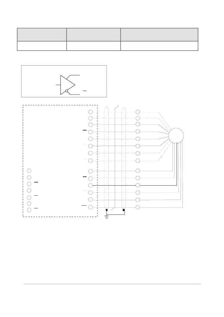
3. Types of Pulse Generators (Encoders)
Line driver
Q
Q
Z/O
0V
A/O
A/O
B/O
B/O
Z/O
VP
0V
A
A
B
B
Z
Z
PG
EMVL-PGABL
U
U
V
V
W
W
Encoder
4. Output Signal Setting of the Frequency Divider
It generates the output signal of division factor
“n” after dealing with the input pulse. Please
set by the switch SW1 on the card.
RESERVE: reserved bit (PIN1)
I/MODE: input type setting of the division
pulse (PIN 2)
O/MODE: output type setting of the division
pulse (PIN 3)
RST: clock reset bit (PIN 4)
Division factor: setting for division factor n:
1~256 (PIN5~12)
Call 1(800)985-6929 for Sales
Call 1(800)985-6929 for Sales

 Loading...


