Chapter 4 Parameters|VFD-VL
4-79
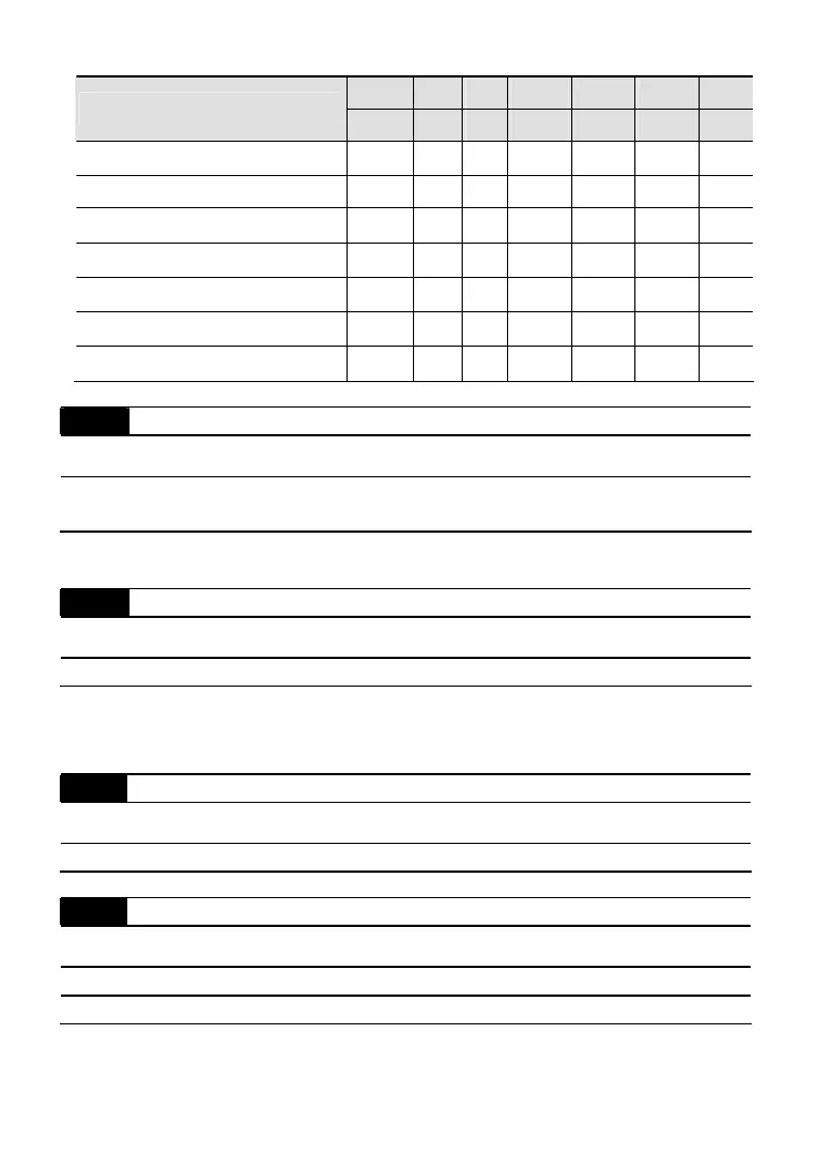
Bit0 Bit1 Bit2 Bit3 Bit4 Bit5 Bit6
Fault code
current Volt. OL SYS FBK EXI CE
60: Brake chopper error (bF)
●
61-62: Reserved
63: Safety loop error (Sry)
●
64: Mechanical brake error (MBF)
●
65: PGF5 hardware error
●
66: Magnetic contactor error (MCF)
●
67: Phase loss of drive output (MPHL)
●
06-26
PTC (Positive Temperature Coefficient) Detection Selection
Control
mode
VF VFPG SVC FOCPG TQCPG FOCPM
Factory setting: 0
Settings 0 Warn and keep operating
1 Warn and ramp to stop
It is used to set the treatment after detecting PTC.
06-27
PTC Level
Control
mode
VF VFPG SVC FOCPG TQCPG FOCPM
Factory setting: 50.0
Settings 0.0 to 100.0%
It is used to set the PTC level, and the corresponding value for 100% is max. analog input
value.
06-28
Filter Time for PTC Detection
Control
mode
VF VFPG SVC FOCPG TQCPG FOCPM
Factory setting: 0.20
Settings 0.00 to 10.00 sec
06-29
Voltage of Emergency Power
Control
mode
VF VFPG SVC FOCPG TQCPG FOCPM
Factory setting: 48.0/96.0
Settings 48.0~375.0Vdc
96.0~750.0Vdc
Call 1(800)985-6929 for Sales
Call 1(800)985-6929 for Sales

 Loading...


