Appendix B Accessories|VFD-VL
B-25
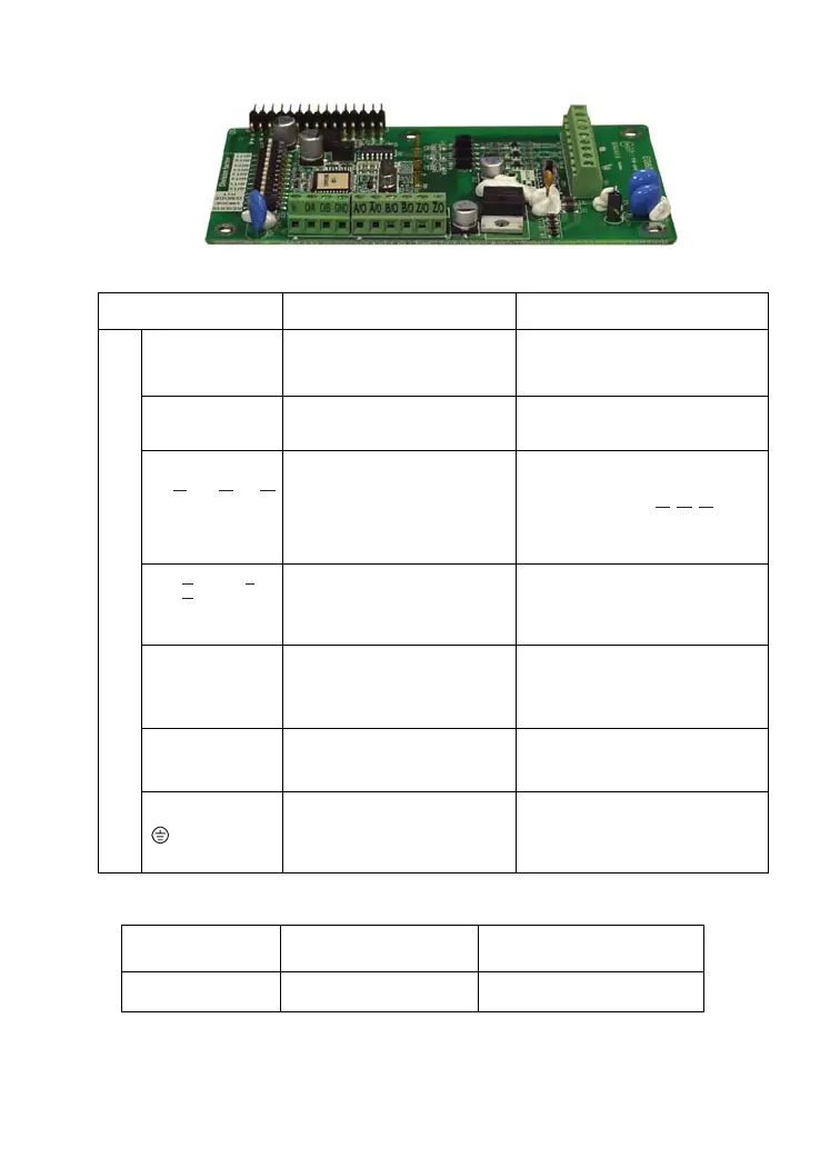
Terminals descriptions
Terminal Symbols Descriptions Specifications
VP
Power source of encoder
Voltage: +12V±1V
Current: 200mA max.
0V
Power source common for
encoder
Reference level of the power of
encoder
A, , B, , Z,A B Z
Incremental line driver input
Open collector signal input.
Max. bandwidth is 100kHz
Please notice that
,
,
A B Z
and
0V should be short circuit.
A/O,
, B/O,
B
Z/O
Z
A
/O
/O,
/O
Pulse output for PG feedback
card and can be used as a
frequency divider.
Line driver RS422
Max. output frequency: 100 kHz
O/A、O/B
Pulse output for PG feedback
card and can be used as a
frequency divider.
Open loop
Max. output frequency 100kHz
Max. 24Vdc, 50mA
Vc
Signal output for power input
side
Voltage: +24V±1V
Current : 50mA
TB1
Grounding
Connected to the grounding of the
power of the AC motor drive and
used for PG shielding
2. Wire length
Output Type of the
Encoder
Maximum Wire Length Wire Gauge
Open collector 50m 1.25mm
2
(AWG16) or above
Call 1(800)985-6929 for Sales
Call 1(800)985-6929 for Sales

 Loading...


