Chapter 2 Installation and Wiring|VFD-VL
2-4
230V models: VAC: 100 to 230
V DC: 140 to 32 5
460V models: VAC: 200 to 380
VDC: 280 t o 537
Specifications for
1-phase UPS or battery
EPS/+
R/L1
S/L2
T/L3
EPS/-
MI1~8
COM
1
2
3
1
2
3
48Vdc (230V Series)
96Vdc (460V Series)
3
~
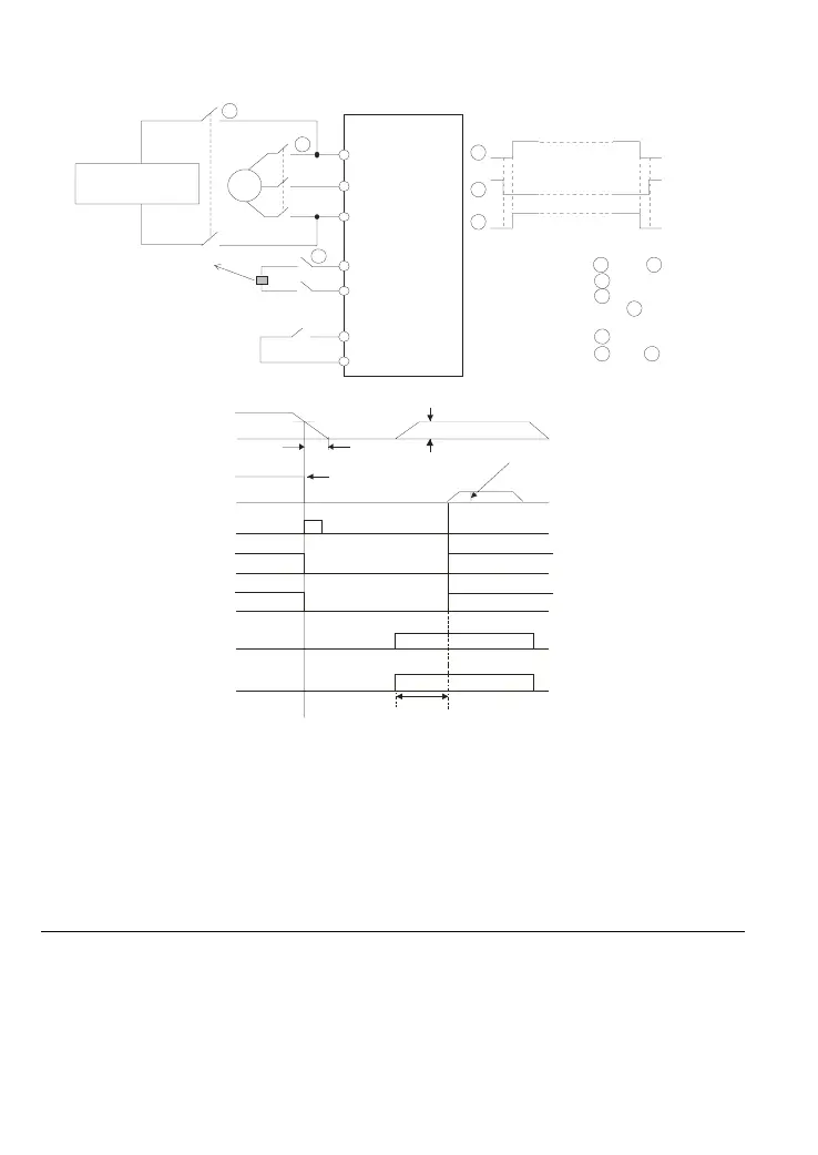
Before inputting emergency power,
ma gne ti c c ontact or a nd are ON and
magnetic contactor should be OFF.
Magnetic contactor should be ON
after ma gnetic contac tor is ON .
Before removing battery and turn
magnetic contactor to be ON,
ma gne ti c c ontact or a nd sho uld be
OFF.
Timing diagram of M.C.
(magnetic contact or)
AC motor drive
Main
power
To input emergency power
1-phase UPS or battery
Figure 4 Apply to two batteries with main battery voltage is lower than 280Vdc
1 3
1 3
2
3
1
2
DC voltage
low voltage level
battery voltage
free run
motor speed
operation command
electromagnetic
valve, MO-COM=15
about 1 min.
mechanical brake
about 2 sec.
EPS operation frequency
Refer to Pr.06-44)
drive
ready
EPS
detection
OFF
MI-COM=43
ON
ON
MO-COM=9
error output
MO-COM=11
Notes for the emergency power supply. Please be aware of the following condition when emergency
power is ON:
1. Fan doesn’t run
2. Parameter setting will not be saved, when the power is turned off and applies again, the
parameter setting will be gone.
3. Operate by the speed set in Pr.06-48.
4. No protections for low voltage and phase loss
5. Display DC-BUS voltage by Pr.06-29
Call 1(800)985-6929 for Sales
Call 1(800)985-6929 for Sales

 Loading...


