SERVICE MANUAL
Installation
(Rev. 0) RTG PLUS (120V)
6-5
14. Fix the cables dedicated brackets in the rear lower part of the
column; remove the packing material that is blocking the arm
rotation and the counterweight stop pin.
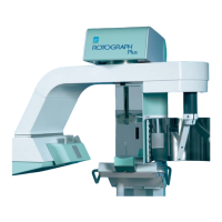
15. Position the sliding group in low position, then insert one
counterweight "A" in the proper housing.
Figure 6-7
NOTE:
The two counterweights “A” are smaller than counterweights “B”.
The counterweights “B” have to be used with Ceph version (see
paragraph 6.3).
16. Fasten the cables in the rear part of the column by means of the
dedicated brackets, making them turn as shown in Figure 6-9 and
connecting X1 and X7 connectors in the control panel lower and
upper part.
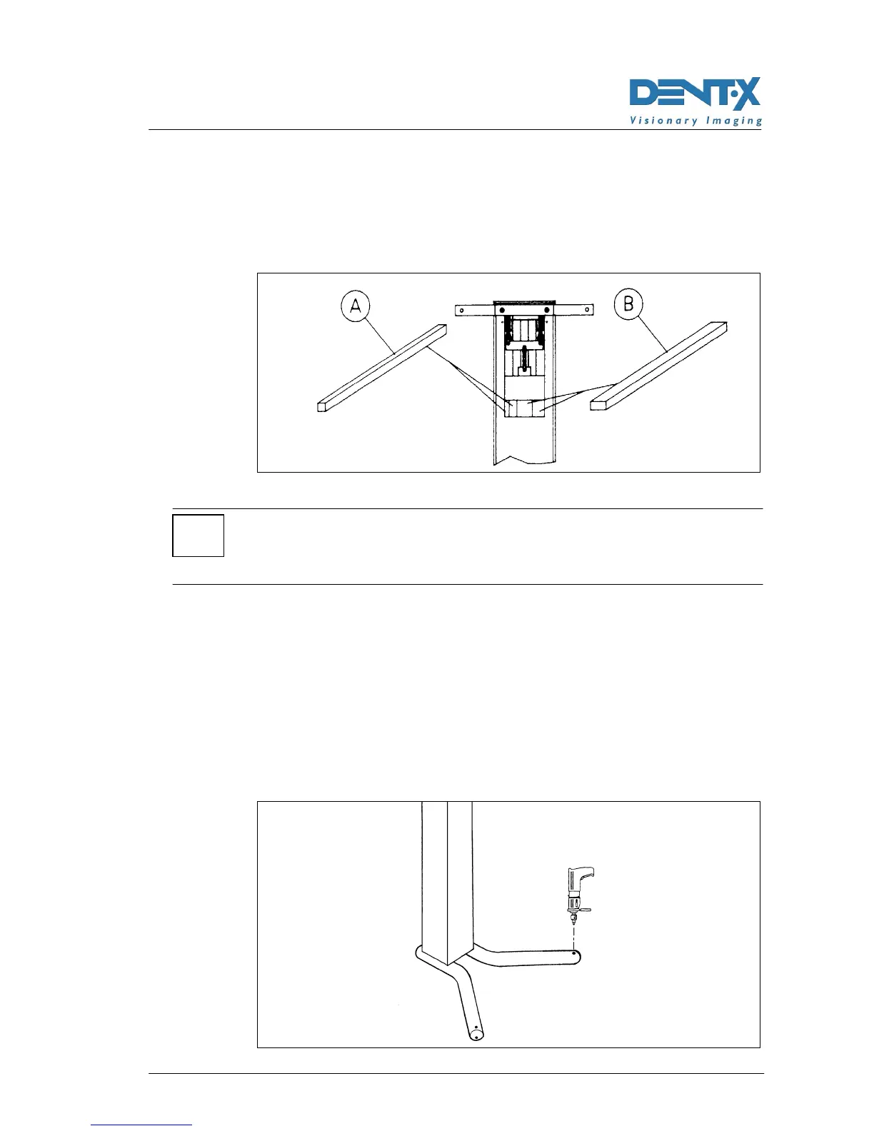
17. Check the perpendicularity of ROTOGRAPH PLUS adjusting the 4
levelling screws located under the legs and assemble the support
with the appropriate clamp.
18. Secure the unit to the floor by drilling the necessary 2 holes in the
floor through the relevant predisposed holes on the legs, and using 2
8mm dowels (outer diameter = 8mm) provided with the unit (see next
Figure).
Figure 6-8
*