SERVICE MANUAL
Checkout and adjustments
(Rev. 0) RTG PLUS (120V)
7-9
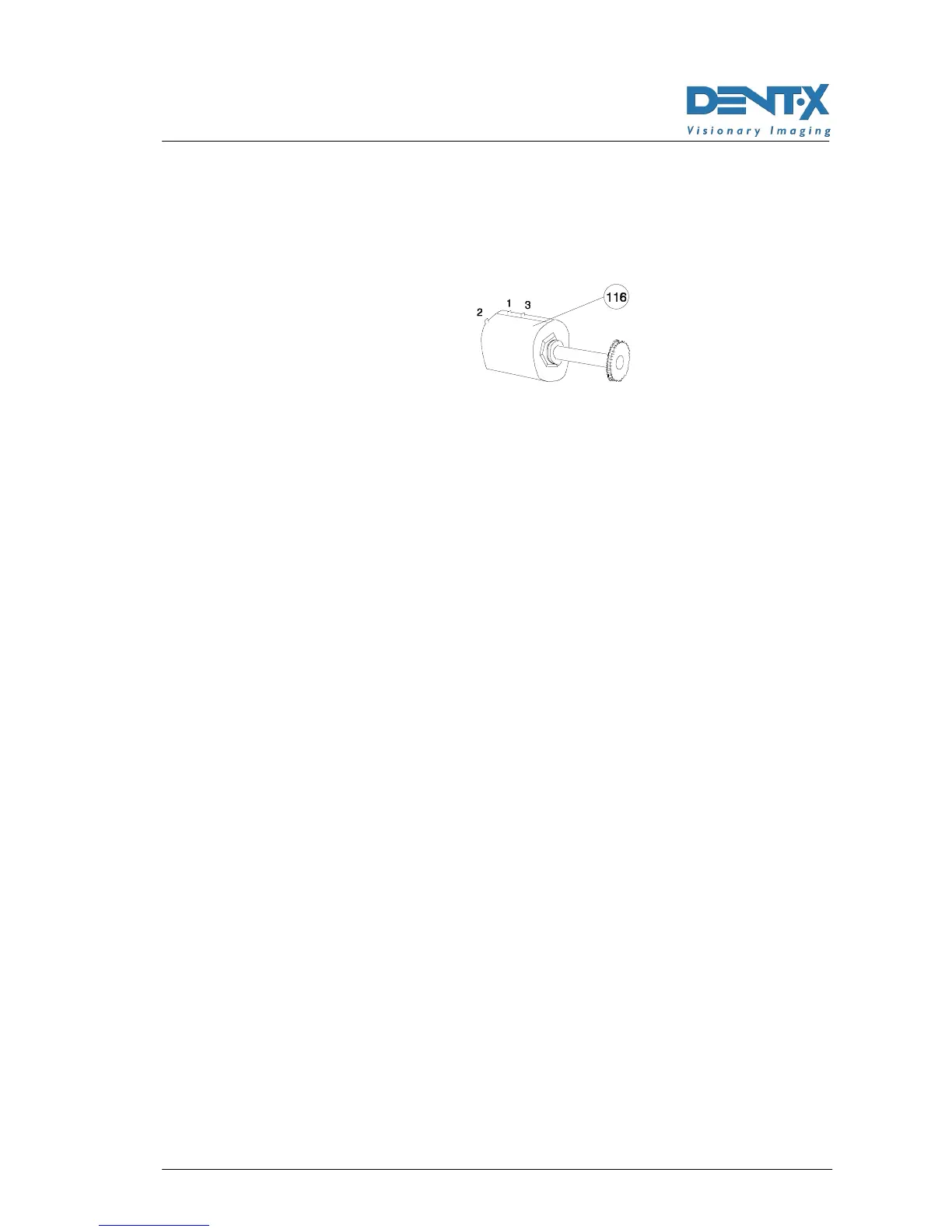
4. Depending on the value of the potentiometer, adjust it to read
between pins 2 and 3 (see next Figure) a value of 350Ω±10 (for 5kΩ
potentiometer), 700Ω±20 (for a 10kΩ potentiometer) or 1400Ω±30
(for a 20kΩ potentiometer).
5. Install the potentiometer on the unit.
6. Manually bring the arm to the central position and lock the clutch.
7. Connect cable X1, turn ON the unit and wait for the end of the initial
self-test.
8. Press the "R" key (32; Reset); the arm will rotate up to reach the
0° position.
9. Switch OFF the unit ; switch it back ON by activating the set-up
function (see above Note 2) and press the "T" (31) button: the display
will shown A/D followed by a number; press the "decrease" key (40)
to store the value corresponding to the 0° position.
10. Press key "T" (31) to store the value.
11. Rotate the arm by pressing and holding the "T" key (31) checking
that the angle at the end of the rotation is 245° and that the cammes
(135, 136) are aligned, check that the middle lines (134) are aligned
(see Figure 7-4 page 7-20).
12. Turn OFF the unit, switch it back ON by activating the set-up
program (see above Note 2).
13. Press the "T" (31) key; the system will show on the remote-control
display the reading of the A/D Converter corresponding to the
angular position of the potentiometer (and therefore given by the
relevant resistance value); at this point the display should indicate
223 (equivalent to 2.23 V) or a value approximate to this number.
14. Press the "increase" (41) key to store into memory this value as
value corresponding to the 245° position of the rotating arm.
15. Press the "T" (31) key to store the value and exit the set-up program.
16. Press the "R" (32) key to bring the arm in starting position.
17. Switch the unit OFF, then back ON, activate the set-up programs
(see above Note 2) and press the "s" (39) key.
18. Press the "T" (31) key several times until showing SA OFF