Page 168 Configuring Frame Relay 90030500B
What is Frame Relay?
Frame Relay was adapted from the Link Access Protocol D-Channel (LAPD) of the
ISDN model. It is a switched digital service, in which several
virtual
or
logical
cir-
cuits share a common
physical
circuit. Each physical circuit connects to a Frame
Relay service provided by the service provider; this service is sometimes referred to as
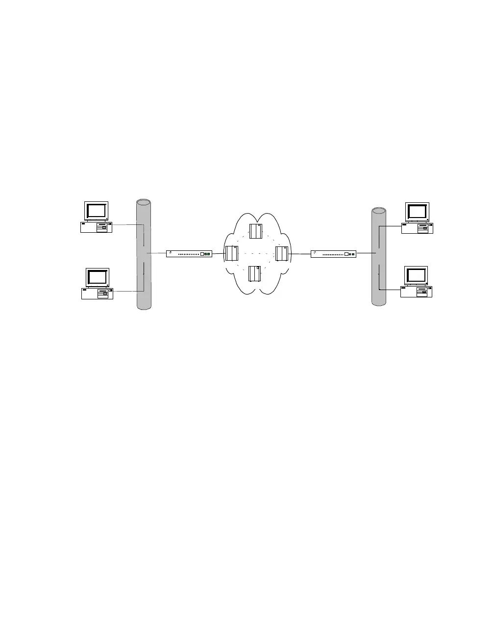
the “cloud”. This arrangement allows a server to make a “logical” connection to sev-
eral other servers that are also connected to the service, but utilizing only one physical
circuit.
Figure 21 Typical Frame Relay Configuration
Each logical connection is referred to as a Permanent Virtual Circuit (PVC). Each
PVC has a Data Link Channel Identifier (DLCI) associated with it. The DLCI is used
locally to identify the connection, but does not traverse the network. The DLCI is
converted and mapped between its origin and its destination, according to a scheme
specified by the network service provider, and may change each time it passes through
a network switch. A DLCI differs from an address because each data frame only
identifies a circuit in each direction, not a source and destination.
Frame Relay networks incorporate error detection, but not error recovery, to permit
faster data throughput. Because this scheme does not guarantee delivery of packets,
several flow control mechanisms are provided to minimize the possibility of network
overflow. (If the network overflows due to buffer pools being full, it may drop
packets because of the lack of error recovery.) Three mechanisms are available to
control flow:
1. The network service provider specifies the Committed Information Rate (CIR),
which is the rate in bytes-per-second that data should be successfully delivered by
the network, under normal conditions.
PortServer II
16
PortServer
Frame Relay
Service
Ethernet
User Terminal
16
PortServer
User Terminal
User Terminal
User Terminal
Ethernet
PortServer II
DLCI
DLCI
FR Switch
FR Switch
FR Switch
Fr Switch
 Loading...