90030500B Operation Page 25
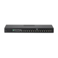
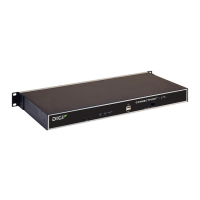
PortServer II Side and Rear Panels
The connectors for the Ethernet cable, the power on/off switch, and the D.C. power
supply are located on the left-hand side panel of PortServer II (viewed from the front),
while the serial port connectors are on the rear panel. The locations of connectors are
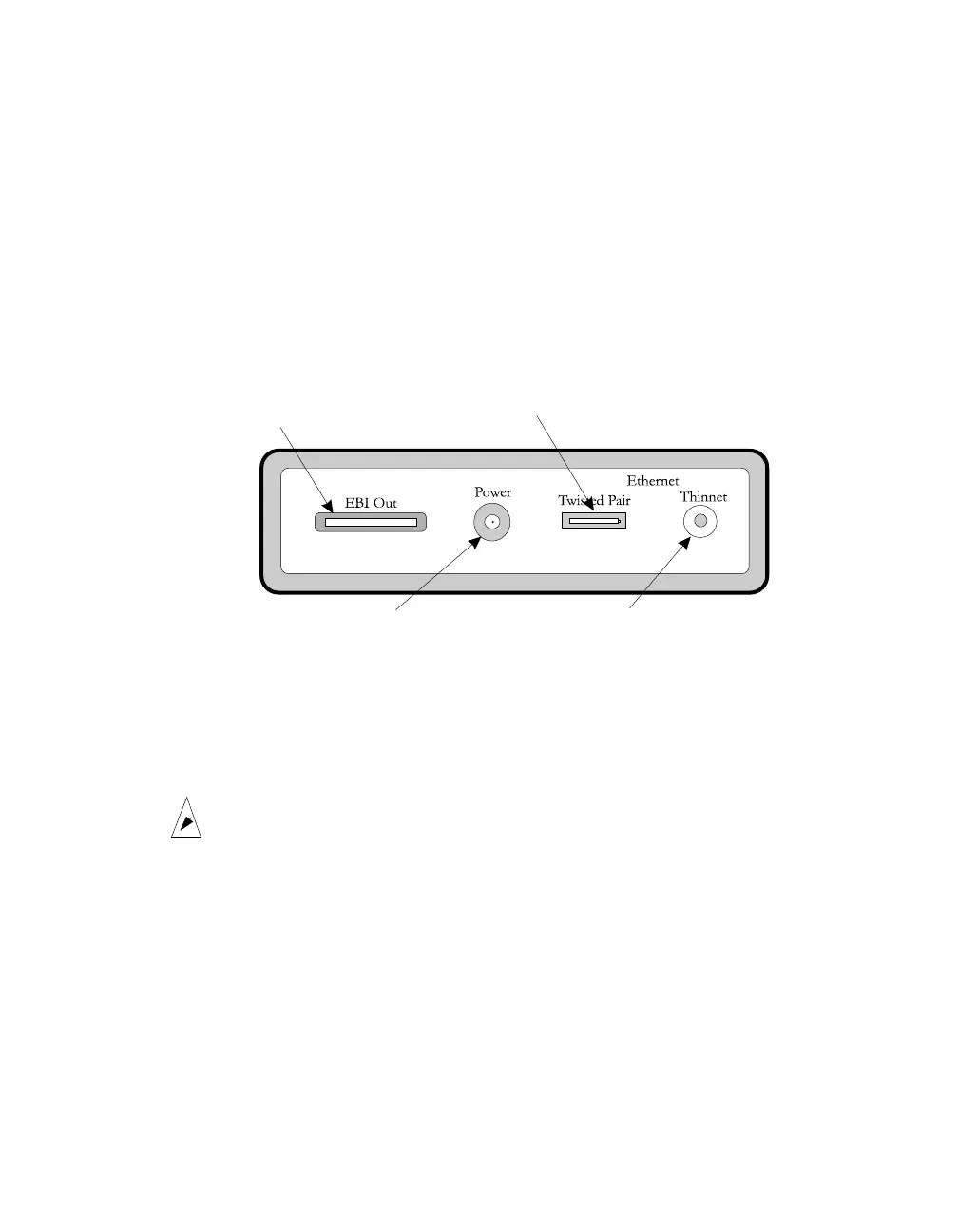
shown below:
Side panel
Figure 8 PortServer II Side Panel
Power on/off switch and socket
The D.C. power connector from the power unit provided with PortServer II should be
inserted in this socket. Use the switch to turn the PortServer II on or off.
Caution!
This switch does not disconnect power from the PortServer II
power unit and there may be 110V/220V power present on the
power unit when this switch is set to 0 (off). Take care if you are
doing installation or service work.
EBI Out connector
This is provided for the connection of a compatible expansion module from the Digi
International PORTS range. Refer to the expansion module documentation for more
details.
Expansion Module
Connector
Power Socket
10BaseT Connector
10Base2 Connector