15
SD12 - Getting Started
1-15
1.4 Hardware Conguration
1.4.1 Connections ............................................................................
Detailed information on the various systems of connection is provided in the relevant chapter of this and the "Software Reference"
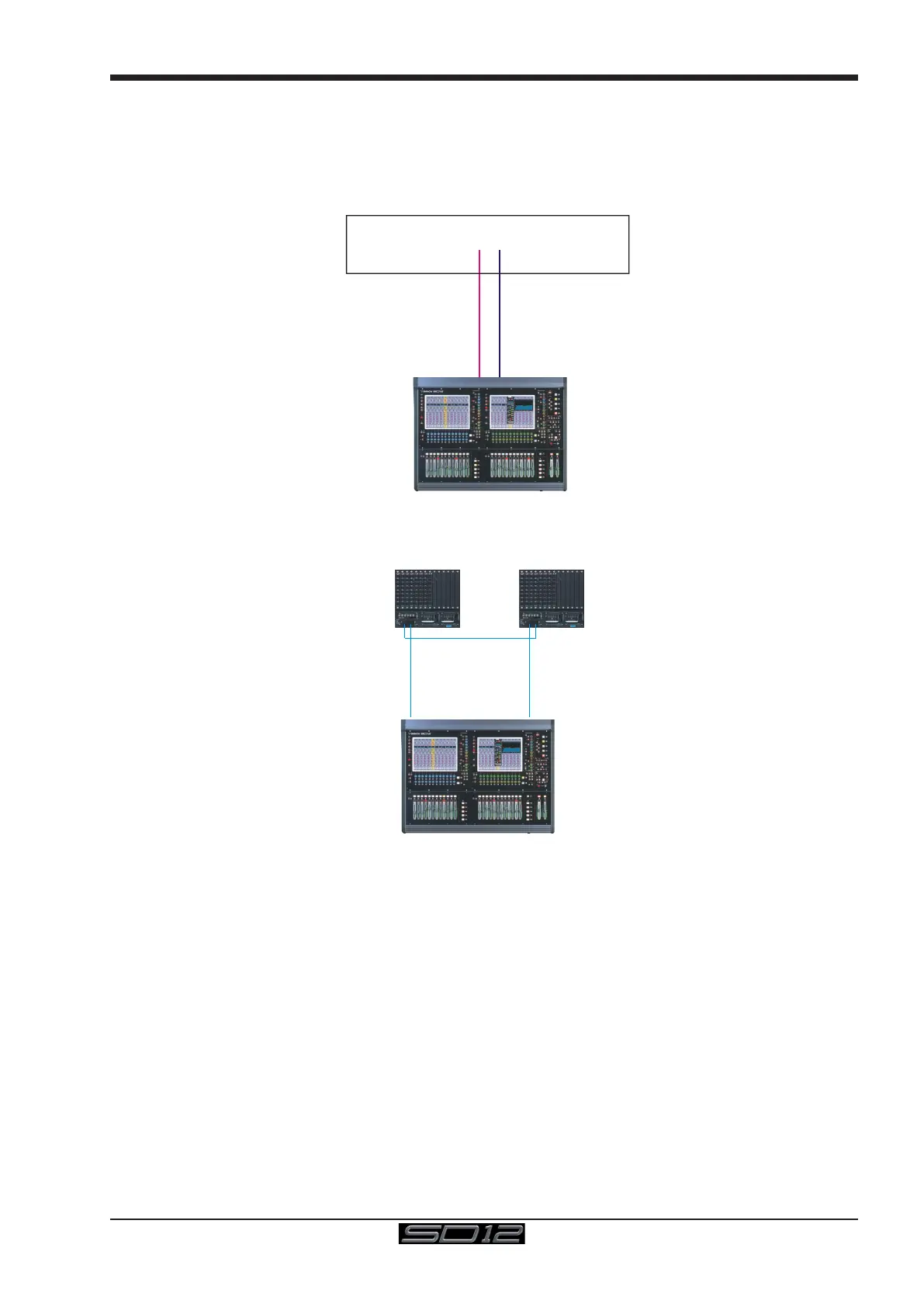
manual but the following diagram provides an overview of a single console/single rack setup
MAIN MADI IN
CONNECTION WITH MADI
CONNECTION WITH OPTICAL FIBRE
OPTO A
OPTO A
OPTIONAL
REDUNDANT
LOOP
OPTO A
OPTO B
OPTO B
OPTO B
M
A
D
I P
O
R
T
1
O
U
T
M
A
D
I P
O
R
T
1
IN
MAIN MADI OUT
SD Rack / DiGiRack
All connections should be made before switching on the console and racks.
The console and rack each have dual redundant power supplies and both should be switched on at all times. After switching on the
console the software will be launched automatically and the state of the worksurface and settings should be the same as when it was
last Shut Down.
To Shut Down the console press the System>Shut Down button and wait until you receive a message saying that it is safe to switch
the power off.
The SD12 worksurface has 8 analogue I/O and 8 AES I/O on its rear panel (referred to as Local I/O) and additional I/O is supplied in the
form of remote Racks which can each accommodate up to 56 inputs and 56 outputs in different formats. These racks are connected to
the worksurface by either 100M high specication 75 Ohm coaxial cables tted with BNC connectors or optical bre. The Racks have
two pairs of MADI connectors - Main MADI IN & OUT and AUX MADI IN & OUT.
In normal operation the MADI connections should be as follows (see diagram above):
Rack MAIN MADI IN connected to the console MADI 1 OUT
Rack MAIN MADI OUT connected to the console MADI 1 IN
At 48KHz, the console's other MADI Port can be connected to a MADI recorder (See Audio I/O Panel for setup details) or a second
DiGiCo Rack or console.