17
SD12 - Getting Started
1-17
from the channels in the session. This is especially useful when restructuring an existing session to make a new session. The other
'clear' buttons in the display perform similar operations.
Aux Sends and Direct Sends : By toggling the state of the Aux Sends and Direct Sends Buttons in the Input Channels section, it is
possible to change the default operation of the Aux Sends and Direct Sends. These functions toggle between “Post Fader”, “Pre-Fader”
and “Pre-Mute”.
Aux Order and Group Order : The Aux Order and Group Order buttons open a second window, providing you with the ability to change
the order of auxes and groups. By default, mono busses come rst, followed by stereo busses. The Master buss is the rst stereo buss,
regardless of the order you place the busses in.
Auto-Route : The Auto-route functions automatically routes consecutive inputs for input channels, and consecutive outputs for busses.
For example, auto-routing 72 inputs will route the rst physical input (eg 1:Mic 1) to input channel 1, the second physical input (1:Mic 2)
to input channel 2… until you either run out of inputs or channels. Auto-routes are as follows :
Input Channels auto-route with physical inputs
Aux, Group and Matrix Channels auto route to physical outputs
Matrix Inputs auto-route with group outputs
NOTE : Auto-Routing can only be used in conjunction with the “Clear All” button.
Rebuild Banks : When changing the number of allocated channels in any section (input channels, busses etc), you can restructure the
session without rebuilding banks, meaning that any additional channels you have allocated will not be “placed” on the worksurface, and
need to be manually assigned to faders. If however, you restructure a session with Rebuild Banks (either Horizontally or Vertically)
enabled, the worksurface will be built with all channels available on the worksurface in a default layout. Rebuilding horizontally will result
in input channels being spread across the top layer of both sides of the console, using as many banks as required, with output channels
being assigned to Layer 2. Rebuilding vertically will result in input channels being assigned to Layer 1 on the left side of the console,
and output channels to Layer 1 on the right.
1.5.3 Audio I/O Overview .................................................................
The Audio I/O window is used to congure the physical I/O connected to the SD12, including conguring and naming the sockets of the
option cards installed in racks, and the setting of Pads and phantom power.
Local I/O : The SD12 provides local audio I/O on the rear of the console. These operate independently of connected racks, providing
additional audio I/O.
To access the SD12 Audio I/O Setup Touch “Setup” on the Master Screen, followed by “Audio I/O”
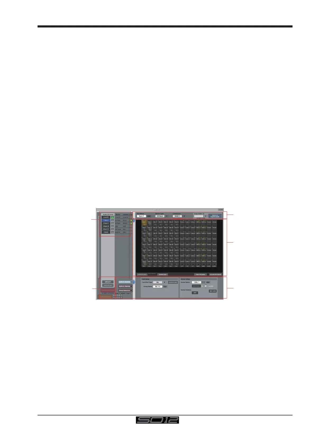
The Audio I/O window that opens is divided up into the following sections
Port Selection
and Status
Global Port
Management
Configuration of
Cards & Sockets
Splits & Sharing,
Or Optocore,
as defined by
buttons to the left
Graphic
Representation of
Selected Rack
Selected Port’s
Properties
The top-left corner of the window shows the ports. Each port relates to an available physical audio connection (Local IO, IO Rack, or
MADI Port, USB Audio (UBMADI), DMI cards). Ports can be added and removed using the buttons towards the bottom-left corner of the
window.
NOTE: Please refer to the DMI card section of this document for more details on the use of DMI cards in the system
The top-right area contains the controls relating to specic ports. When a port is selected, this section changes to reect the status of
the selected port, and allows its conguration to be changed as required.
Most of the right-hand section of the panel consists of a graphical representation of the rack conguration connected to the selected
port. Depending on the port selected, the graphic will change, showing the available physical I/O. Each small “square” on the image
represents a single physical audio connection or socket, with these arranged in columns or rows, representing I/O cards in racks, or the
local I/O on the back of the console.
The section below the graphical rack picture allows conguration of either the cards or slots and sockets (including custom naming,
phantom power and pad selection), or card splits and control sharing. The Cards & Sockets and Splits & Sharing buttons dene which
elements are displayed for conguration.
The local I/O conguration is xed, so no hardware changes are possible. You can, however, change the Port Name, the Group Names
(relating to the name of each physical card) and the Socket Names (the name of each physical connector on a card).