Aligning the Video Monitor 4–9
5. Slowly turn the G2, or SCREEN, (Figure 4–5) clockwise until the
radiance meter shows a value of .002 to .004; the raster is not visible.
6. Set brightness to minimum (counter-clockwise).
7. The screen should be totally blank; if not, repeat steps 1 through 6.
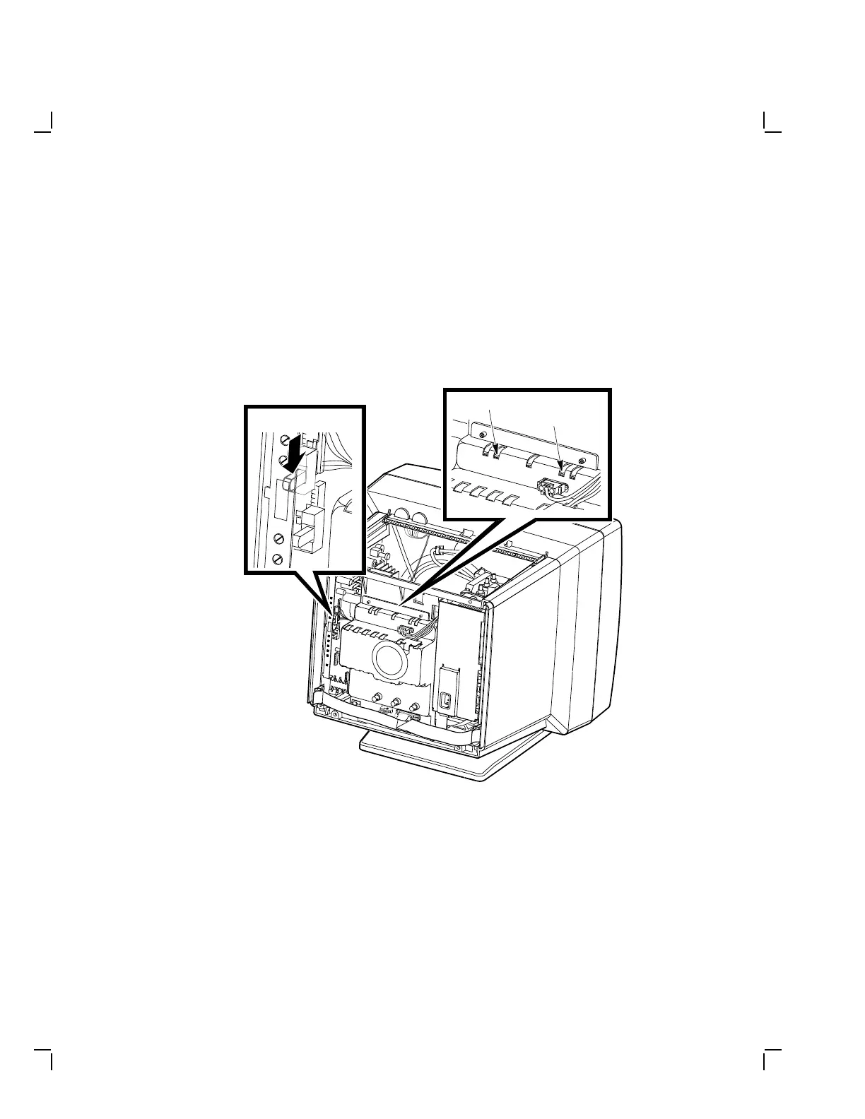
8. Set the service switch (Figure 4–7) on the deflection module to
SERVICE (down position).
MA-1351-89.DG
Service Switch (Down)
Red Cutoff
Blue Cutoff
Figure 4–7 Service Switch and Blue and Red Cutoff


 To Next Page