DIGITAL-LOGIC AG PCCP5 Manual V2.3
90
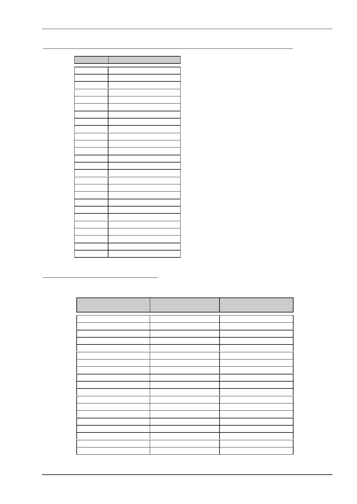
J11 Optionally assembled on the rear side for micro floppy 3,5" (26 pins FCC-header
Pin Signal
Pin 1 = VCC
Pin 2 = Index
Pin 3 = VCC
Pin 4 = Drive select
Pin 5 = VCC
Pin 6 = Disk change signal
Pin 7 = nc
Pin 8 = nc
Pin 9 = nc
Pin 10 = Motor on
Pin 11 = nc
Pin 12 = Dir
Pin 13 = nc
Pin 14 = Step
Pin 15 = GND
Pin 16 = Write data
Pin 17 = GND
Pin 18 = Write gate
Pin 19 = GND
Pin 20 = Track 00
Pin 21 = GND
Pin 22 = Write protect
Pin 23 = GND
Pin 24 = Read data
Pin 25 = GND
Pin 26 = Head select
J18 Printerport connector (LPT1)
The printer connector provides an interface for 8 bit centronics printers.
Since V1.2 Header onboard D-SUB connector
on the cable
Signal
Pin 1 Pin 1 = Strobe
Pin 3 Pin 2 = Data 0
Pin 5 Pin 3 = Data 1
Pin 7 Pin 4 = Data 2
Pin 9 Pin 5 = Data 3
Pin 11 Pin 6 = Data 4
Pin 13 Pin 7 = Data 5
Pin 15 Pin 8 = Data 6
Pin 17 Pin 9 = Data 7
Pin 19 Pin 10 = Acknowledge
Pin 21 Pin 11 = Busy
Pin 23 Pin 12 = Paper end
Pin 25 Pin 13 = Select
Pin 2 Pin 14 = Autofeed
Pin 4 Pin 15 = Error
Pin 6 Pin 16 = Init printer
Pin 8 Pin 17 = Shift in (SI)
Pin 10,12,14,16,18 Pin 18 – 22 = Left open
Pin 20,22,24 Pin 23 – 25 = Ground