DIGITAL-LOGIC AG PCCP5 Manual V2.3
96
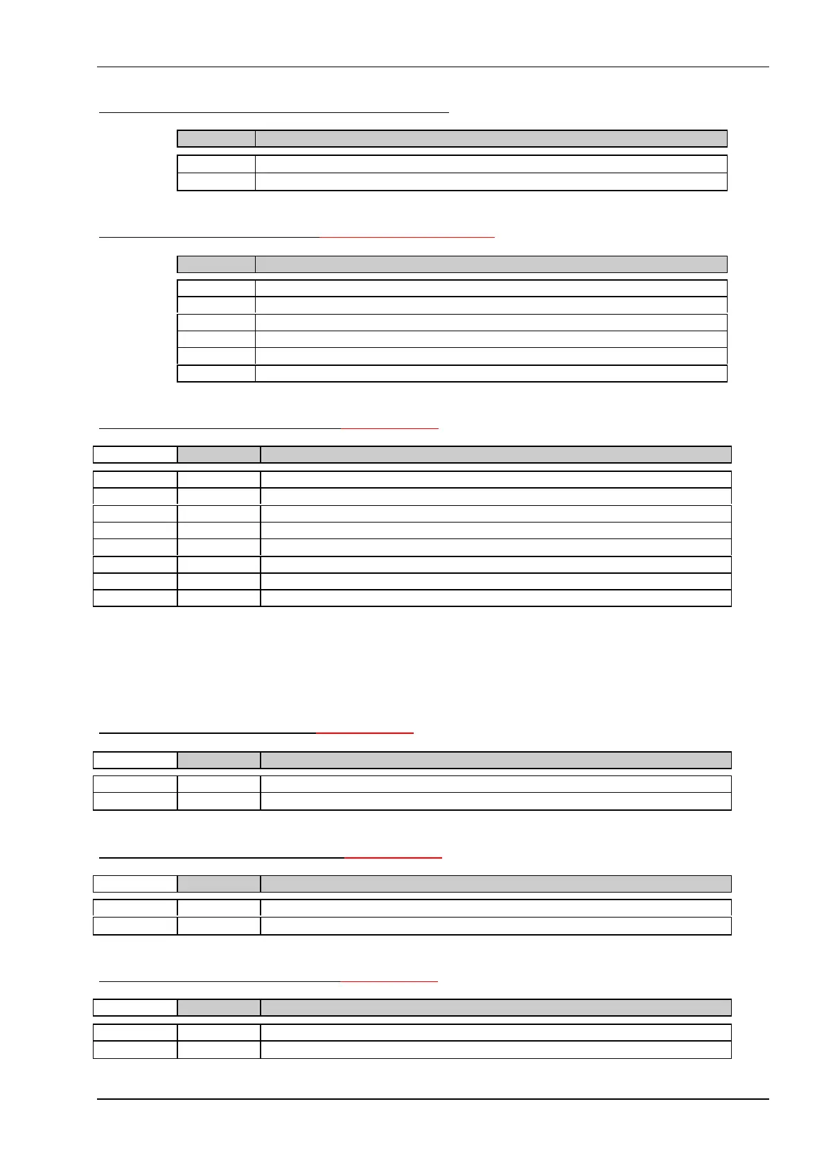
J58 Temperature connector, ext. NTC resi stor
Pin Function
Pin 1
NTC resistor, e.g. 100 kΩ
Pin 2
NTC resistor, e.g. 100 kΩ
J97 Dual USB connector, NOT SUPPORTED by BIOS
Pin Function
Pin 1 VCC
Pin 2 USB Port 0+
Pin 3 USB Port 0-
Pin 4 USB Port 1+
Pin 5 USB Port 1-
Pin 6 Ground
J95 AUI Interface connector, new since V2.3
Pin Signal
Pin 1 +12V
Pin 2 GND
Pin 3 Collision +
Pin 4 Collision -
Pin 5 Receiver +
Pin 6 Receiver -
Pin 7 Transmitter +
Pin 8 Transmitter -
- This signals must be isolated with a Ethernet transformator (PE64103 from Pulse Engineering or similar)
and amplified with an National 8392C circuit for the coaxial connector.
Please ask DesignIn Center of DIGITAL-LOGIC to get a sample schematics for the 10BASE-2 applica-
tion.
J98 LAN LED connector, new since V2.3
Pin Signal
Pin 1 BSE (cathode)
Pin 2
BSE (anode), 470Ω resistor to Vcc included
J99 IDE HDD LED connector, new since V2.3
Pin Signal
Pin 1 ACTP- (cathode)
Pin 2
ACTP- (anode), 470Ω resistor to Vcc included
J102 POWER LED connector, new since V2.3
Pin Signal
Pin 1 Vcc (anode)
Pin 2
470Ω resistor to GND included