Page 51
AIM 2 Operation Manual
Installing an ODU
Chapter 6
Overview
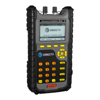
The AIM guides you through the steps for aligning and performing follow-up Extended
Installation Verication (EIV) for each ODU.
Aligning the ODU
The tasks for aligning an ODU vary depending on the type of ODU. All ODU types require
coarse adjustments to be made in the azimuth and elevation directions. The 95° ODU also
requires an adjustment in the tilt direction. To make coarse adjustments, move the ODU
in the appropriate direction and use the AIM to determine the position that obtains the
maximum possible signal power.
Slimline ODUs require ne adjustments (dithering) to be performed in the azimuth and
elevation directions to further hone the signal power. To dither, rotate the ne adjustment
jack screws to:
• Obtain a “reference” signal power on one side of the beam peak
• Obtain the identical strength on the other side of the beam peak
• Split the difference between the two reference points to obtain the maximum signal
power for all applicable orbital slots.
The AIM guides you through the dithering process using a series of audible tones to notify
you when the reference values have been obtained.
The DIRECTV training materials are the primary source of
ODU installation instruction. Those documents supersede the
instructions in this manual.
If you encounter an issue during the installation process and
want to save information for reference later, you can capture
an image of the AIM screen and save it as a record. See the
Chapter 3: Capturing a Screenshot section.

 Loading...