1.3 PAD CONSTRUCTION
The 1601 and 1602 operators are designed to be mounted directly to a concrete pad. The size of the
pad specified below will allow four inches of clearance around the operator. This will prevent the pad
from splitting or cracking when anchoring the operator to the pad.
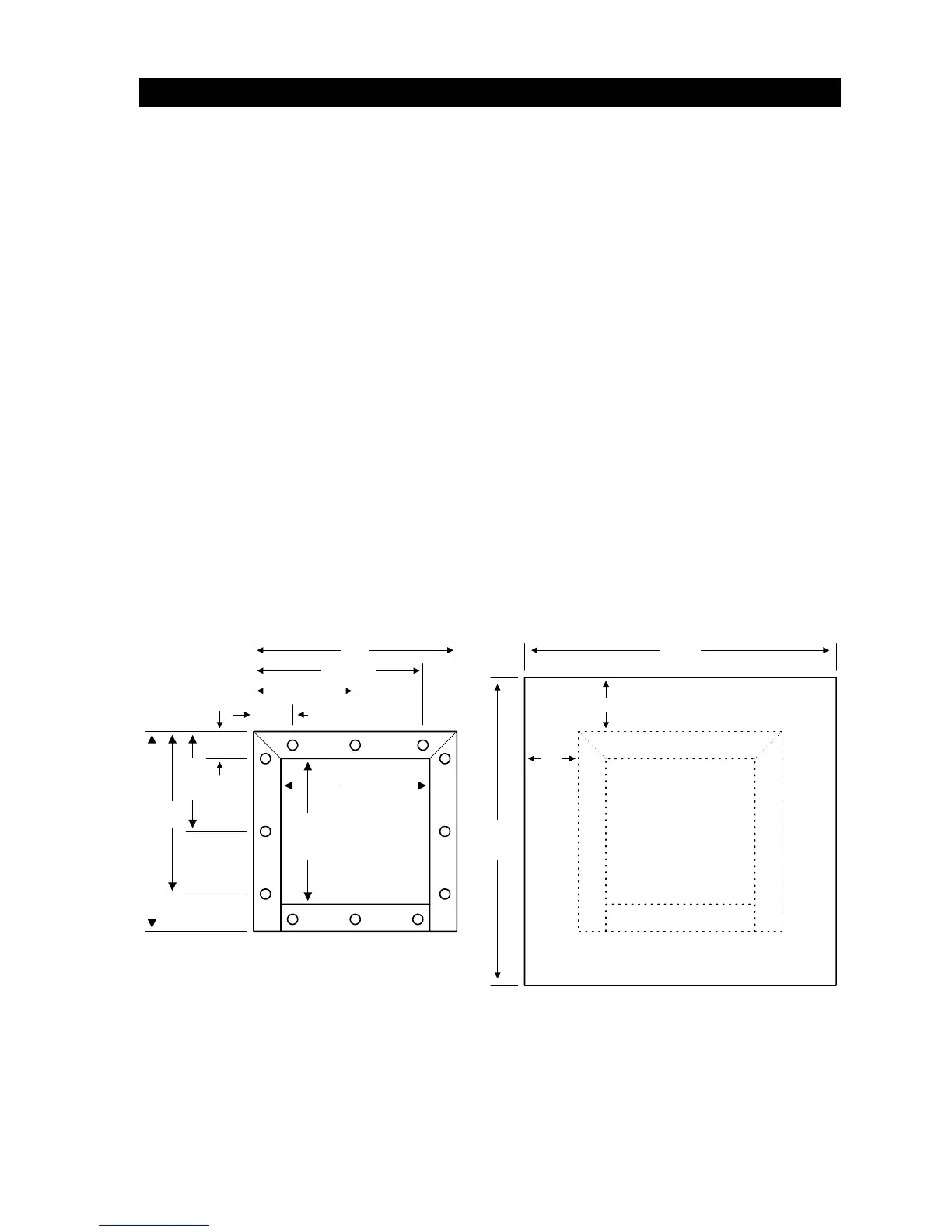
1. Construct a form for the mounting pad according to the figures shown in the diagram
below. Be sure to level the top edge of the form. The depth of the pad is determined by
local soil conditions and local building codes, but should be at least 24 inches deep. We
suggest that you contact the local building department to determine the proper depth of
the pad.
2. Construct the form so that the top level of the pad is at least four inches above ground
level. This will help prevent water from accumulating in the bottom of the operator.
3. Set conduits to center of pad (see below) and reinforcing bars and/or wire mesh if
desired. The number of conduits is determined by the application requirements. Four
conduits are shown below - one for high voltage power, one for low voltage control
requirements, one for loop lead-in wiring, and one for sequencing control wiring or
master/slave application.
4. Mix concrete according to the manufacturers instructions. Pour the mixture into the form
and tamp. Level and finish the surface after pouring is complete. Do not set anchor bolts
in the concrete. Sleeve anchors can be used to anchor the operator to the concrete after
it has hardened and will allow you to position the operator on the pad exactly where you
want it.
5. Allow the pad to cure for 48 hours before removing the forms or mounting the operator.
11
10.75
14.75
12
7.25
2.5
2.625
7.5
12.375
15 23
23
Base Detail
Mounting Holes
Mounting Pad
4
4
Figure 3
11