2.3.4 GATE TRACKER™ WIRING
This barrier operator is equipped with outputs from the circuit board that will report operator status to
a companion DoorKing Access Control System (Model 1803PC, 1815, 1817 or 1818) that is equipped
with a Tracker expansion board. This report includes items such as operator cycle count, any shorted
inputs, loop detector problems, power interruptions, etc.
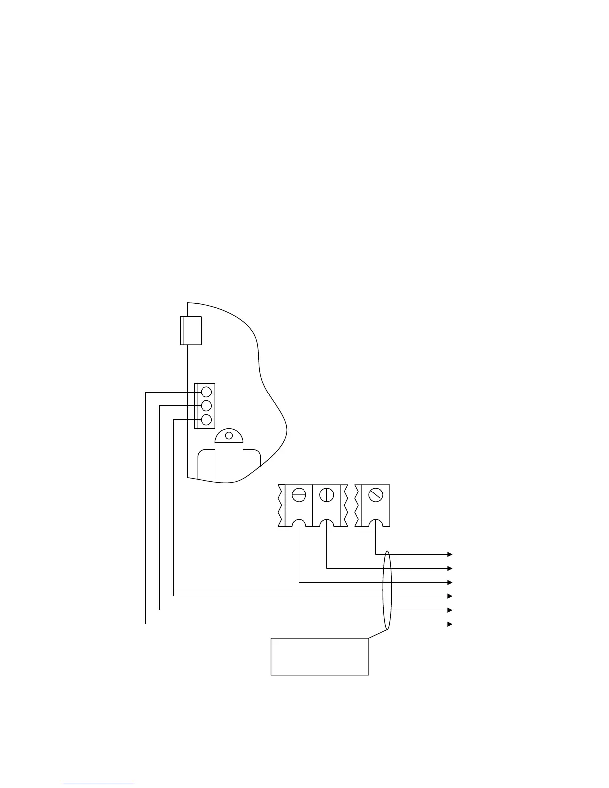
The Gate Tracker™ connections are made at the auxiliary terminal strip located on the left side of the
circuit board, and at terminals 5, 6 and 14 on the main terminal strip. For more detailed information
on Gate Tracker™ and wiring to the Tracker expansion boards, refer to the Tracker Installation and
Wiring Manual, DoorKing P/N 2351-010.
• Maximum wire run for gate operator data to the tracker board is 500 feet using Belden #9931
shielded cable or Consolidated #5324-CL shielded cable. Float the shield at the tracker
board. Do not connect the shield to the tracker board common.
• Wire connection from the tracker board terminal P1-6 to the 1601 / 1602 main terminal 6 is
optional if the barrier operator is not to be activated by the tracker output relay.
5 6 14
P1-5, P2-11
P1-6
P2-12
P2-5
P2-4
P2-3
To Tracker Board
Belden #9931 or
Consolidated #5324-Cl
shielded cable or equivalent.
1601 Main Terminals
1601 Circuit
Board
3 - DATA OUT
2 - DATA IN
1 - COMMON
Figure 13
20