2.4 LOOP DETECTOR WIRING
Loop detector wiring is shown for DoorKing model 9405 and 9406 Plug-In loop detectors only. If
other loop detectors are used, refer to the wiring diagrams that are included with the detectors.
• Be sure that power is turned off prior to making any connections to the terminal strip.
• If other loop detectors are used, all inputs to the terminal strip are NORMALLY OPEN.
• Loop layouts shown are for typical barrier gate applications.
• Refer to the separate Loop Information Manual (available from DoorKing) for instructions on
installing loops or preformed loops.
Ground
Power
Neutral
AC
PWR
DC
PWR
Cntr
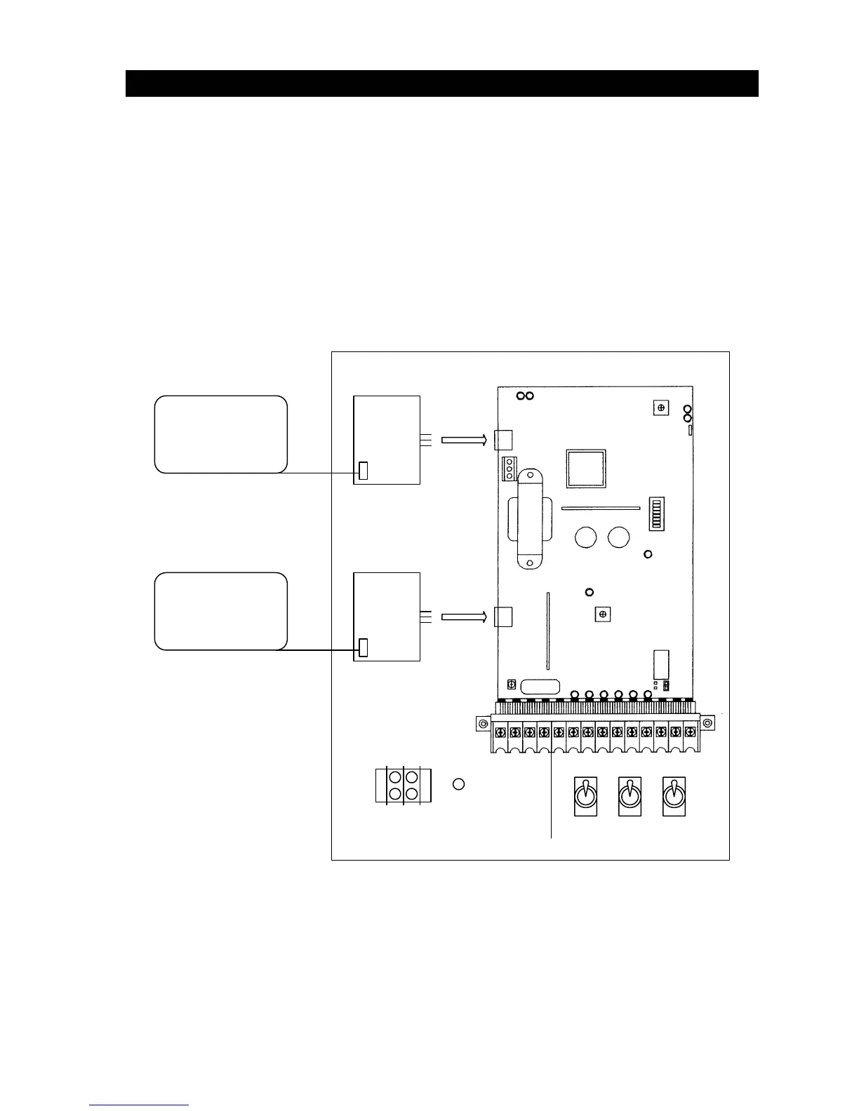
UP
Detector
TB 1
DOWN
Detector
TB 1
Up Loop
Down Loop
Figure 14
21