2.2 HIGH VOLTAGE WIRING
Use Table 1 to determine high voltage wire size requirements. The distance shown in the chart is
measured in feet from the operator to the power source. If power wiring is greater than the maximum
distance shown, it is recommended that a service feeder be installed. When large gauge wire is
used, a separate junction box must be installed for the operator connection. The wire table is based
on stranded copper wire. Wire run calculations are based on a 3% voltage drop on the power line,
plus an additional 10% reduction in distance to allow for other losses in the system.
WIRE SIZE / DISTANCE IN FEET MODEL VOLTS AMPS
12 AWG 10 AWG 8 AWG 6 AWG
1601 120 5.4 170 275 460 685
1601 230 2.7 685 1100 1830 2750
1601 460 1.35 2875 4600 7665 11500
1602 120 14.0 130 210 350 530
1602 230 7.0 530 845 1415 2120
1602 460 3.5 1110 1775 2955 4435
Table 1
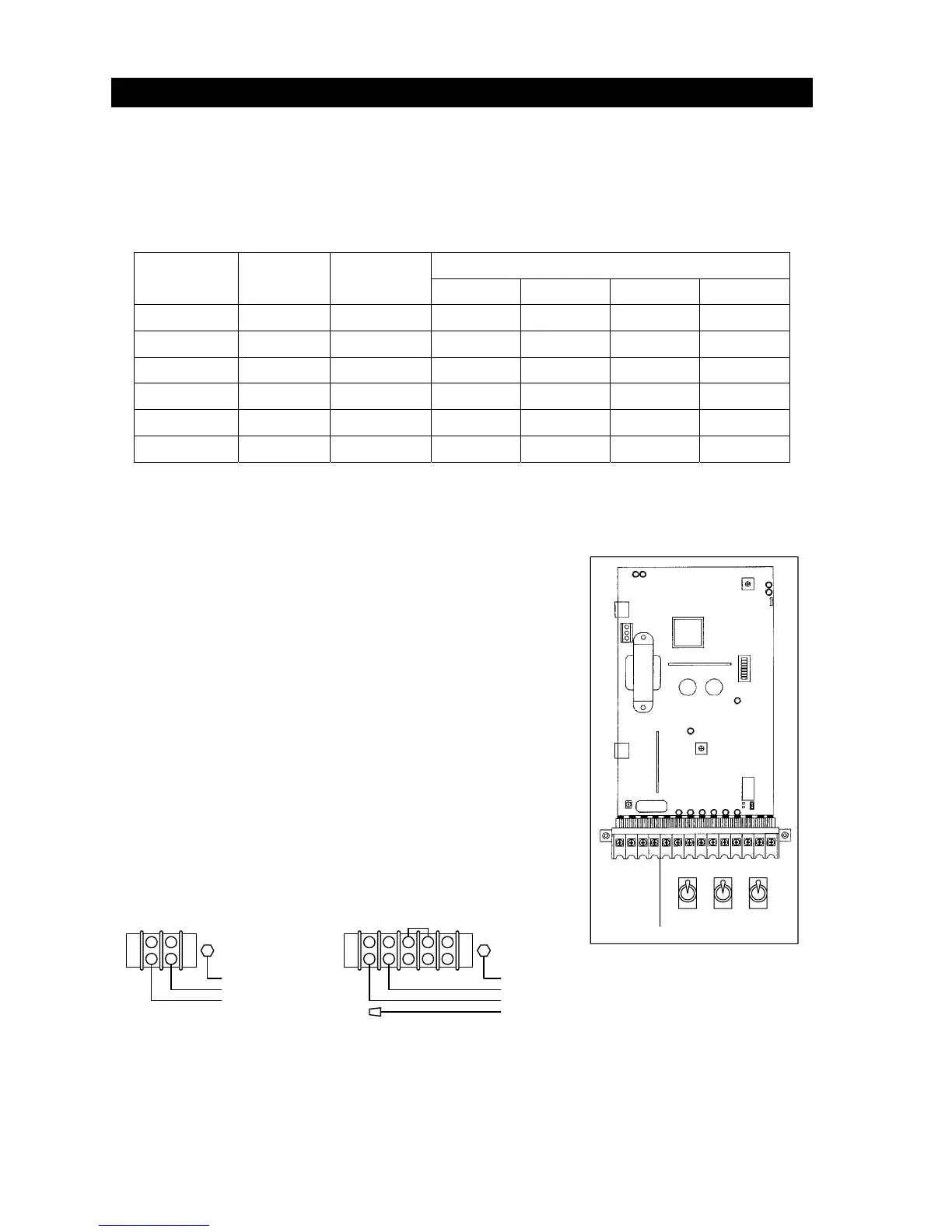
• Route incoming high voltage power through conduit and
into the operator as shown.
• Be sure wiring is installed in accordance with local codes.
Be sure to color code all wiring.
• Connect incoming power to terminal block as shown.
• It is recommended that a surge suppresser be installed
on the high voltage power lines to help protect the
operator and circuit board from surges and power
fluctuations.
• NOTE 1: For 230 and 460 Volt 3-phase input power, use
only two legs of the incoming 3-phase power.
AC
PWR
DC
PWR
Cntr
120 VAC HOT
120 VAC NEUT
120 VAC HOT
120 VAC NEUT
120 VAC NEUT
220 / 460 VAC
GROUND
GROUND
BLACK
WHITE
GREEN
BLACK
BLACK
WHITE
120 VAC 220 / 460 VAC
BLACK
1
Figure 8
16