SECTION 3 – ADJUSTMENTS
The switch settings and adjustments in this chapter should be made after your installation and wiring
to the operator(s) is complete. Whenever any of the programming switches on the circuit board are
changed, power must be shut-off, and then turned back on for the new setting to take effect.
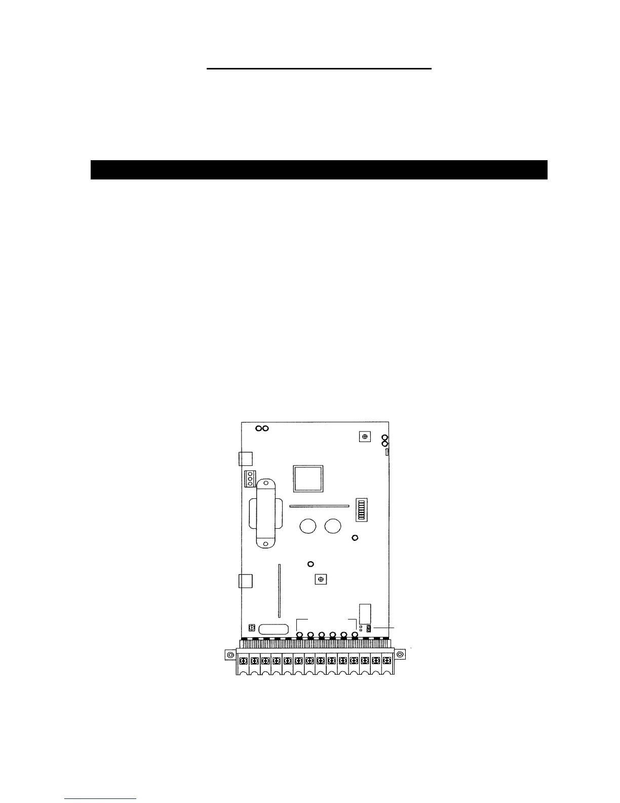
3.1 CIRCUIT BOARD ADJUSTMENTS
• Set the DIP-switches on the circuit board to the desired setting. See switch-setting charts in
section 3.2.
• Auto close timer (when turned on) can be set from 1 second (full counter clockwise) to
approximately 23 seconds (full clockwise).
• Rotate the ERD potentiometer clockwise to increase sensitivity, counter clockwise to
decrease sensitivity.
• Dry contact relay contacts (terminals 12-13) can be set for Normally Open (NO) or Normally
Closed (NC) operation by placing the relay shorting bar on the NO or NC pins respectively.
• Power LED indicates that low voltage power is applied to the circuit board. The input LEDs
should be OFF and will only illuminate when the input is activated.
• Limit LEDs will be ON when the arm is in the respective position.
• Tracker and COMM LEDs indicate data communication to the Tracker board.
21 3 4 5 6 7 8 9 10 11 12 13 14
Time Delay
UP Loop Port
DOWN Loop Port
Gate Tracker
Data Terminals
Earth Ground
Reverse Sens LED
Reverse Sens Adj
Power LED
Programming
Switches
UP Limit LED
DOWN Limit LED
Tracker
Comm LED's
Relay Contact
Shorting Bar
Input LED's
Figure 20
29