CT100 inverter Detailed instructions of function parameters
125
Bus voltage at
current fault
Display the bus voltage at the current
fault
Input terminal
state at
current fault
This value is displayed in decimal digits. Display the
state of all digital input terminals in the current fault.
According to each state transformed into the
corresponding decimal display, when the input
terminal is ON, its corresponding value is 1, OFF is
0.
Output
terminal state
at current fault
This value is displayed in decimal digits. Display the
state of the output terminal at the current fault.
According to each state transformed into the
corresponding decimal display, when the output
terminal is ON, its corresponding value is 1, OFF is
0.
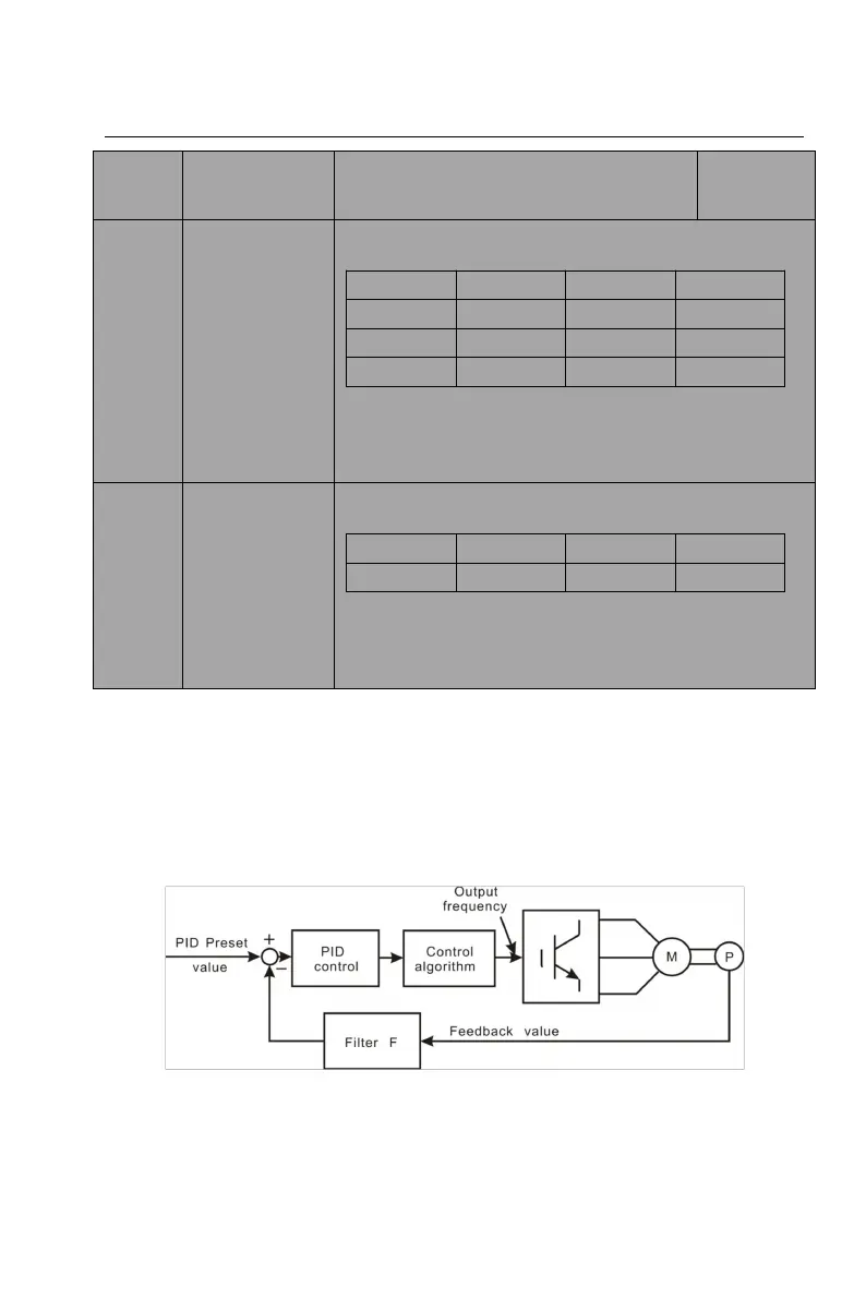
6.10 PID control (F09 group)
PID control is a common method used in process control, such as flow, pressure
and temperature control. The principle will firstly detect the bias between preset
value and feedback value, then calculate output frequency of the system
according to proportional gain, integral and differential time. Please refer to
following figure:
Figure 6-14 PID control
In the system, the PID control is valid only when the X frequency source
reference selection (F0.04) or the Y frequency source reference selection (F0.05)