CT100 series inverters Installation and wiring
40
Short circuit the pins 1 and 2 of X13 by short-circuit module, the
terminal +10V/5V supplies power +10V;
Short circuit the pins 2 and 3 of X13 by short-circuit module, the
terminal +10V/5V supplies power +5V.
Special pins for control board CPU downloading (factory set, unnecessary
to change)
The interface of the main signal for connecting the signals between the
control board and the power board
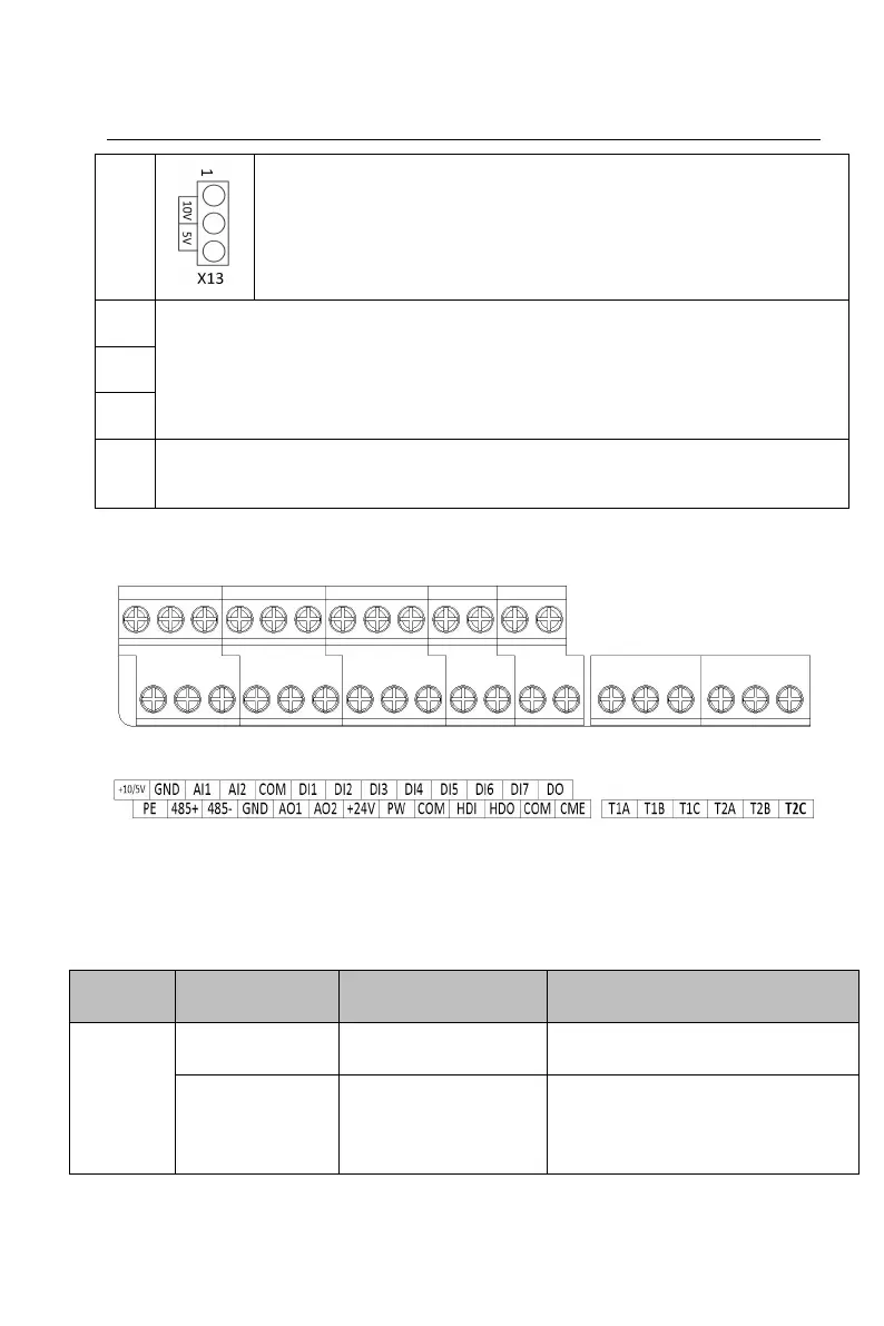
3.8.4 Terminals of control circuit
Figure 3-21 Terminals layout of control circuit
Figure 3-22 Terminals names of control circuit
3.8.5 Functions of terminals in control circuit
Table 3-6 Functions of terminals in control circuit
24V±10%, internal isolation from
GND. Max. load 200mA
External power input
terminal (power
supply of digital
input terminal)
Short circuit with +24V by
default