CT100 series inverters Installation and wiring
39
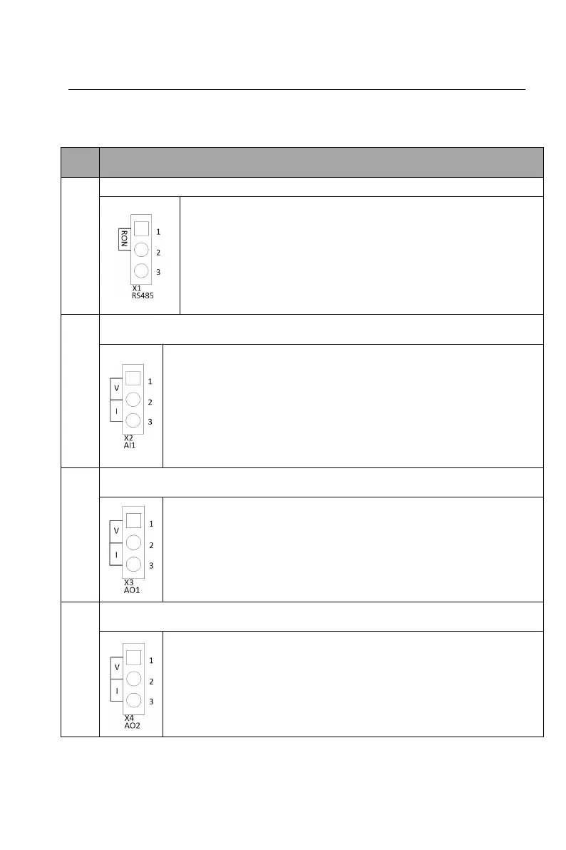
3.8.3 Pins of the control plate
Table 3-5 Pin instructions of the control plate
RS485 terminating resistor setting
Short circuit the pins 1 and 2 of X1 by short-circuit module,
the terminating resistor of 120Ωis used for RS485 bus;
Short circuit the pins 2 and 3 of X1 by short-circuit module,
the terminating resistor is not used for RS485 bus;
When the short-circuit module is not used, the terminating
resistor is not used for RS485 bus.
Analog input 1 voltage and current selection
Short circuit the pins 1 and 2 of X2 by short-circuit module, the
analog input 1 is voltage input (0~10V);
Short circuit the pins 2 and 3 of X2 by short-circuit module, the
analog input 1 is current input (0~20mA);
When the short-circuit module is not used, the analog input 1 is
voltage input (0~10V).
Analog output 1 voltage and current selection
Short circuit the pins 1 and 2 of X3 by short-circuit module, the
analog output 1 is voltage output (0~10V);
Short circuit the pins 2 and 3 of X3 by short-circuit module, the
analog output 1 is current output (0~20mA).
Analog output 2 voltage current selection
Short circuit the pins 1 and 2 of X4 by short-circuit module, the
analog output 2 is voltage output (0~10V);
Short circuit the pins 2 and 3 of X4 by short-circuit module, the
analog output 2 is current output (0~20mA).