EasyManua.ls Logo

dolycon CT100 Series - Terminals Wiring of Main Circuit; Terminals of Main Circuit

dolycon CT100 Series
163 pages
Print Icon
To Next Page IconTo Next Page
To Previous Page IconTo Previous Page
Loading...
CT100 series inverters Installation and wiring
28
when the
inverter is
equipped with
external braking
units.
CT100-4T-132G/160P
150
400
400
CT100-4T-160G/185P
185
500
400
CT100-4T-185G/200P
240
630
400
CT100-4T-200G/220P
150*2
630
630
CT100-4T-220G/250P
150*2
630
630
CT100-4T-250G/285P
185*2
800
630
CT100-4T-285G/315P
150*3
800
800
CT100-4T-315G/355P
150*3
800
800
CT100-4T-355G
150*3
1280
960
CT100-4T-400G
150*4
1380
1035
CT100-4T-500G
150*4
1720
1290
Note: When the inverter is built-in with braking units, the power and resistance of
the braking resistors should be as required above the table, otherwise the
damage to the inverter may occur. When the braking resistors are mounted
externally, you need to purchase yourselves.
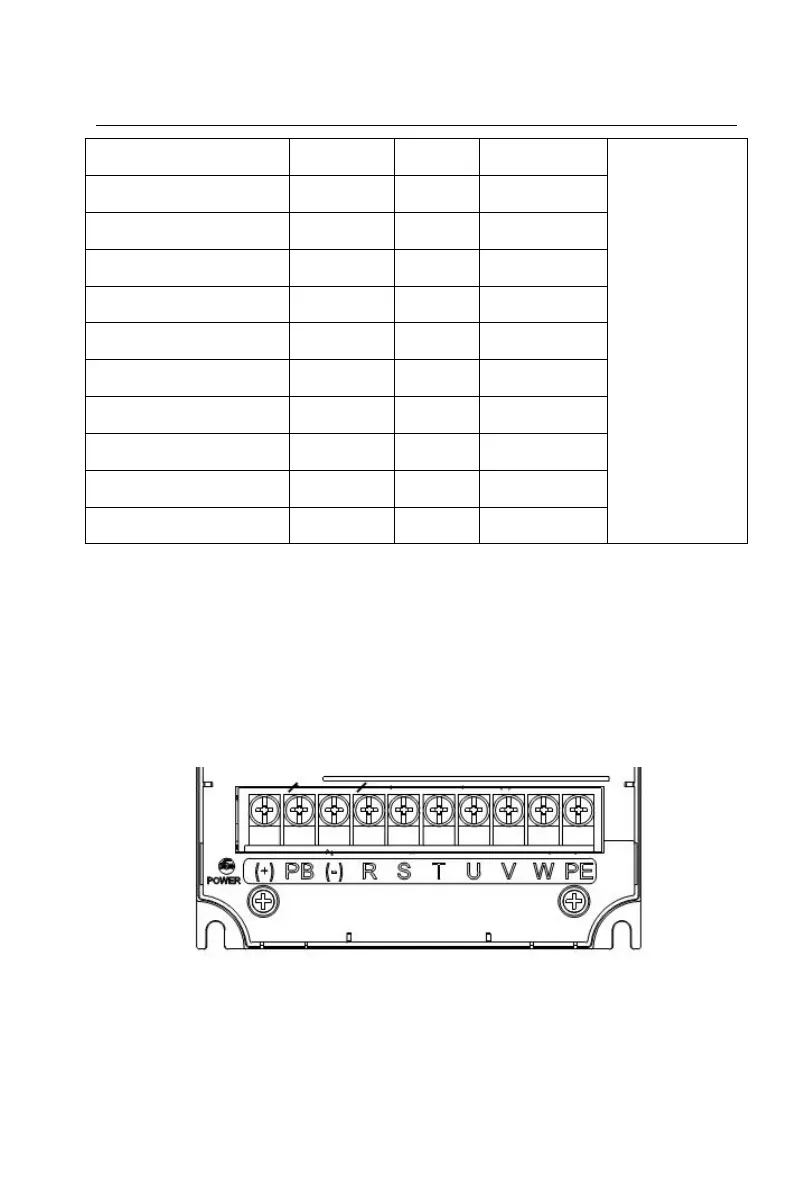
3.5 Terminals wiring of main circuit
3.5.1 Terminals of main circuit
Figure 3-8 CT100-2S-2.2G, CT100-4T-11G/15P and below power

Table of Contents

Related product manuals