CT100 series inverters Installation and wiring
34
2. AC contactor
To cut off the input power of the inverter effectively at system failure, the AC
contactor is needed to be installed at the input side to control the switching on-off
power supply of main circuit safely.
3. Input AC reactor
To prevent the high current flows into the input power circuit and damages the
rectifier part when the grid inputs high voltage, the AC reactor is needed to be
installed at the input side to improve the power factor at the input side.
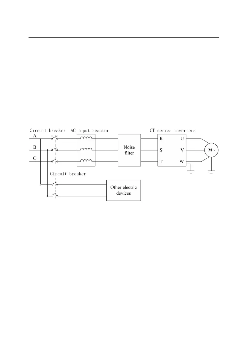
4. Input noise filter
Applying the noise filter can reduce the interference to the peripheral devices
caused by the cables when running the inverter, as shown below:
Figure 3-16 Power supply wiring of main circuit
3.7.2 Inverter wiring of main circuit
1. DC reactor
The CT100 inverter of 15kW~37kW is built-in DC reactor. DC reactor can
improve the power factor and avoid the rectifier circuit damage caused by the
sudden change of the grid voltage or the harmonics of phase control load.
2. Braking unit and braking resistor
The CT100 inverters of the 37kW (including) and below are built-in with braking
units. To consume the feedback energy during braking, it is necessary to connect
the braking resistor between (+) and PB.
The CT100 inverters of the 45kW and above are equipped with external braking
units. To consume the feedback energy during braking, it is necessary to connect
the braking unit between (+) and (-) and the braking resistor between (+) and PB.
The wiring length of the braking resistor should be less than 5m. Pay attention to