CT100 inverter Detailed instructions of function parameters
91
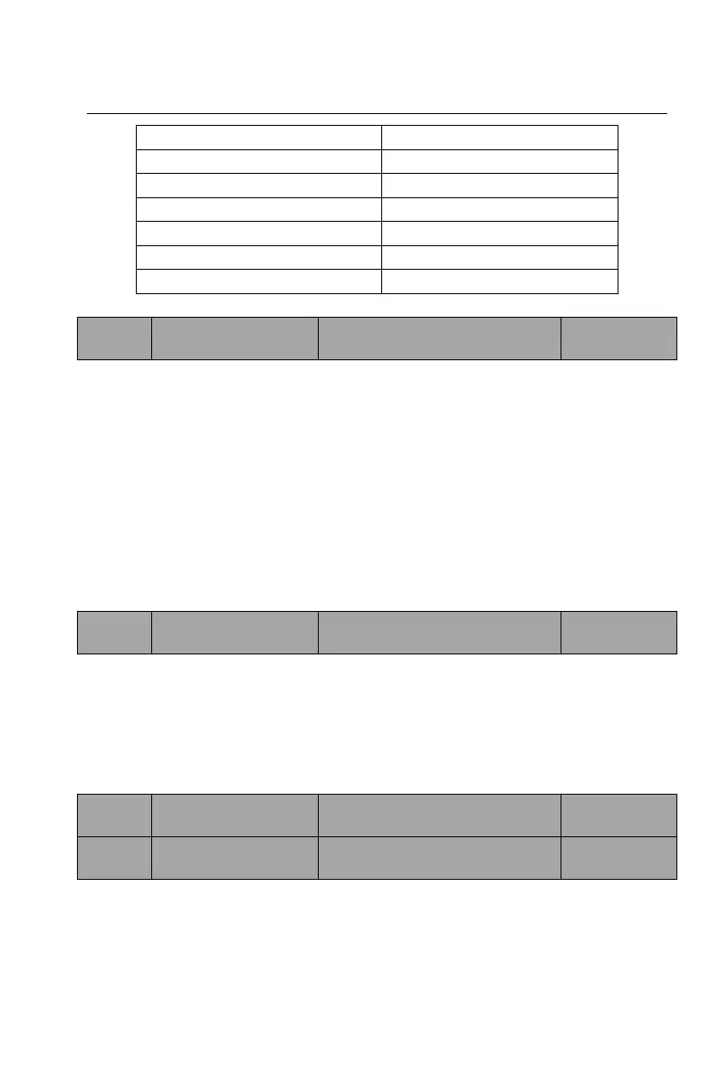
Inverter temperature rise
External radiation interference
Table 6-1 Carrier frequency adjustment impact on performance
0: PWM optimization 1
SVPWM two-phase modulation, the motor runs at low frequency with small noise,
high frequency with large noise.
1: PWM optimization 2
SVPWM two-phase modulation combined with three-phase modulation, the
motor runs with small noise, but the inverter temperature rise is higher, derating
is necessary.
2: PWM optimization 3
SVPWM three-phase modulation, the motor runs with large noise, but the motor
oscillation is suppressed.
0: invalid
The duty cycle of the output voltage does not change.
1: valid
The output voltage duty cycle is automatically adjusted as the bus changes to
ensure that the output voltage is constant.
Setting range: 0.1~3000.0s
Setting range: 0.1~3000.0s
ACC time 0: the time it takes for the inverter output frequency increasing from
zero frequency to the maximum frequency (F00.06).
DEC time 0: the time it takes for the inverter output frequency decreasing from
the maximum frequency to the zero frequency (F00.06).